

328
10 Residual Axial Capacity of UHPCC-FST Column Under …
(a)
(b)
(c)
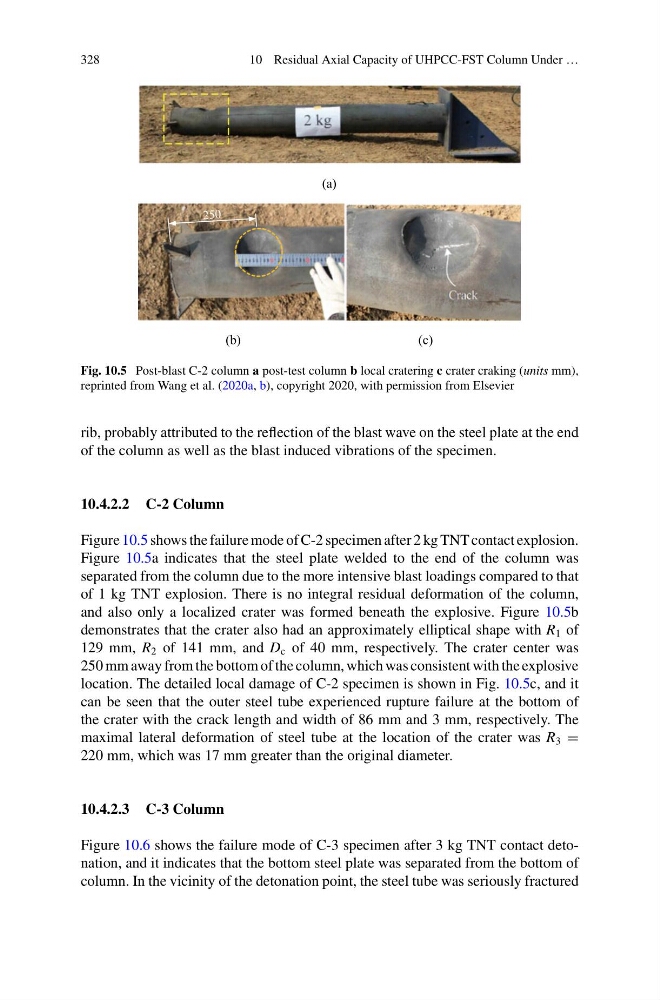
Fig. 10.5 Post-blast C-2 column a post-test column b local cratering c crater craking (units mm),
reprinted from Wang et al. (2020a, b), copyright 2020, with permission from Elsevier
rib, probably attributed to the reflection of the blast wave on the steel plate at the end
of the column as well as the blast induced vibrations of the specimen.
10.4.2.2 C-2 Column
Figure 10.5 shows the failure mode of C-2 specimen after 2 kg TNT contact explosion.
Figure 10.5a indicates that the steel plate welded to the end of the column was
separated from the column due to the more intensive blast loadings compared to that
of 1 kg TNT explosion. There is no integral residual deformation of the column,
and also only a localized crater was formed beneath the explosive. Figure 10.5b
demonstrates that the crater also had an approximately elliptical shape with R 1 of
129 mm, R 2 of 141 mm, and D c of 40 mm, respectively. The crater center was
250 mm away from the bottom of the column, which was consistent with the explosive
location. The detailed local damage of C-2 specimen is shown in Fig. 10.5c, and it
can be seen that the outer steel tube experienced rupture failure at the bottom of
the crater with the crack length and width of 86 mm and 3 mm, respectively. The
maximal lateral deformation of steel tube at the location of the crater was R 3 =
220 mm, which was 17 mm greater than the original diameter.
10.4.2.3 C-3 Column
Figure 10.6 shows the failure mode of C-3 specimen after 3 kg TNT contact detonation, and it indicates that the bottom steel plate was separated from the bottom of
column. In the vicinity of the detonation point, the steel tube was seriously fractured
10 Residual Axial Capacity of UHPCC-FST Column Under …
(a)
(b)
(c)
Fig. 10.5 Post-blast C-2 column a post-test column b local cratering c crater craking (units mm),
reprinted from Wang et al. (2020a, b), copyright 2020, with permission from Elsevier
rib, probably attributed to the reflection of the blast wave on the steel plate at the end
of the column as well as the blast induced vibrations of the specimen.
10.4.2.2 C-2 Column
Figure 10.5 shows the failure mode of C-2 specimen after 2 kg TNT contact explosion.
Figure 10.5a indicates that the steel plate welded to the end of the column was
separated from the column due to the more intensive blast loadings compared to that
of 1 kg TNT explosion. There is no integral residual deformation of the column,
and also only a localized crater was formed beneath the explosive. Figure 10.5b
demonstrates that the crater also had an approximately elliptical shape with R 1 of
129 mm, R 2 of 141 mm, and D c of 40 mm, respectively. The crater center was
250 mm away from the bottom of the column, which was consistent with the explosive
location. The detailed local damage of C-2 specimen is shown in Fig. 10.5c, and it
can be seen that the outer steel tube experienced rupture failure at the bottom of
the crater with the crack length and width of 86 mm and 3 mm, respectively. The
maximal lateral deformation of steel tube at the location of the crater was R 3 =
220 mm, which was 17 mm greater than the original diameter.
10.4.2.3 C-3 Column
Figure 10.6 shows the failure mode of C-3 specimen after 3 kg TNT contact detonation, and it indicates that the bottom steel plate was separated from the bottom of
column. In the vicinity of the detonation point, the steel tube was seriously fractured