

308
9 Dynamic Responses of Reinforced UHPCC Members Under …
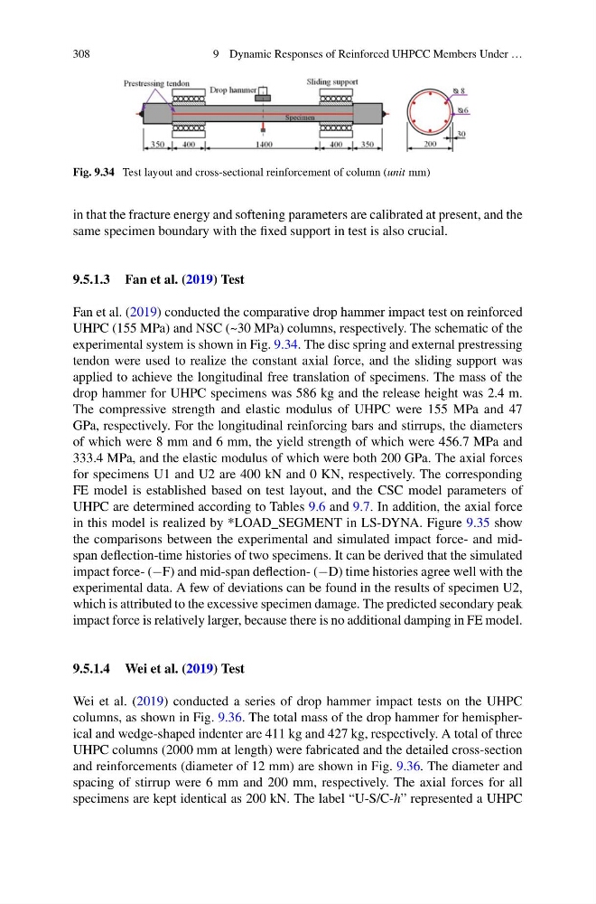
Fig. 9.34 Test layout and cross-sectional reinforcement of column (unit mm)
in that the fracture energy and softening parameters are calibrated at present, and the
same specimen boundary with the fixed support in test is also crucial.
9.5.1.3 Fan et al. (2019) Test
Fan et al. (2019) conducted the comparative drop hammer impact test on reinforced
UHPC (155 MPa) and NSC (~30 MPa) columns, respectively. The schematic of the
experimental system is shown in Fig. 9.34. The disc spring and external prestressing
tendon were used to realize the constant axial force, and the sliding support was
applied to achieve the longitudinal free translation of specimens. The mass of the
drop hammer for UHPC specimens was 586 kg and the release height was 2.4 m.
The compressive strength and elastic modulus of UHPC were 155 MPa and 47
GPa, respectively. For the longitudinal reinforcing bars and stirrups, the diameters
of which were 8 mm and 6 mm, the yield strength of which were 456.7 MPa and
333.4 MPa, and the elastic modulus of which were both 200 GPa. The axial forces
for specimens U1 and U2 are 400 kN and 0 KN, respectively. The corresponding
FE model is established based on test layout, and the CSC model parameters of
UHPC are determined according to Tables 9.6 and 9.7. In addition, the axial force
in this model is realized by *LOAD_SEGMENT in LS-DYNA. Figure 9.35 show
the comparisons between the experimental and simulated impact force- and midspan deflection-time histories of two specimens. It can be derived that the simulated
impact force- (−F) and mid-span deflection- (−D) time histories agree well with the
experimental data. A few of deviations can be found in the results of specimen U2,
which is attributed to the excessive specimen damage. The predicted secondary peak
impact force is relatively larger, because there is no additional damping in FE model.
9.5.1.4 Wei et al. (2019) Test
Wei et al. (2019) conducted a series of drop hammer impact tests on the UHPC
columns, as shown in Fig. 9.36. The total mass of the drop hammer for hemispherical and wedge-shaped indenter are 411 kg and 427 kg, respectively. A total of three
UHPC columns (2000 mm at length) were fabricated and the detailed cross-section
and reinforcements (diameter of 12 mm) are shown in Fig. 9.36. The diameter and
spacing of stirrup were 6 mm and 200 mm, respectively. The axial forces for all
specimens are kept identical as 200 kN. The label “U-S/C-h” represented a UHPC
9 Dynamic Responses of Reinforced UHPCC Members Under …
Fig. 9.34 Test layout and cross-sectional reinforcement of column (unit mm)
in that the fracture energy and softening parameters are calibrated at present, and the
same specimen boundary with the fixed support in test is also crucial.
9.5.1.3 Fan et al. (2019) Test
Fan et al. (2019) conducted the comparative drop hammer impact test on reinforced
UHPC (155 MPa) and NSC (~30 MPa) columns, respectively. The schematic of the
experimental system is shown in Fig. 9.34. The disc spring and external prestressing
tendon were used to realize the constant axial force, and the sliding support was
applied to achieve the longitudinal free translation of specimens. The mass of the
drop hammer for UHPC specimens was 586 kg and the release height was 2.4 m.
The compressive strength and elastic modulus of UHPC were 155 MPa and 47
GPa, respectively. For the longitudinal reinforcing bars and stirrups, the diameters
of which were 8 mm and 6 mm, the yield strength of which were 456.7 MPa and
333.4 MPa, and the elastic modulus of which were both 200 GPa. The axial forces
for specimens U1 and U2 are 400 kN and 0 KN, respectively. The corresponding
FE model is established based on test layout, and the CSC model parameters of
UHPC are determined according to Tables 9.6 and 9.7. In addition, the axial force
in this model is realized by *LOAD_SEGMENT in LS-DYNA. Figure 9.35 show
the comparisons between the experimental and simulated impact force- and midspan deflection-time histories of two specimens. It can be derived that the simulated
impact force- (−F) and mid-span deflection- (−D) time histories agree well with the
experimental data. A few of deviations can be found in the results of specimen U2,
which is attributed to the excessive specimen damage. The predicted secondary peak
impact force is relatively larger, because there is no additional damping in FE model.
9.5.1.4 Wei et al. (2019) Test
Wei et al. (2019) conducted a series of drop hammer impact tests on the UHPC
columns, as shown in Fig. 9.36. The total mass of the drop hammer for hemispherical and wedge-shaped indenter are 411 kg and 427 kg, respectively. A total of three
UHPC columns (2000 mm at length) were fabricated and the detailed cross-section
and reinforcements (diameter of 12 mm) are shown in Fig. 9.36. The diameter and
spacing of stirrup were 6 mm and 200 mm, respectively. The axial forces for all
specimens are kept identical as 200 kN. The label “U-S/C-h” represented a UHPC