

9.4 Numerical Simulation
293
(3) Cap parameters
UHPCC is a type of cement-based composite with internal defect like micro-void,
etc., which is generally compacted and collapsed with increasing the hydrostatic pressure. Thus, the plastic deformation occurs on UHPCC when the pressure reaches
some threshold value, which is described by the cap hardening surface given in
Eq. (9.10) in CSC model. The cap hardening parameters consists of R, X 0 , W,
D 1 and D 2 , which can be fitted by pressure-volumetric strain curves of hydrostatic compression tests. The parameter X 0 is the initial location of the cap where
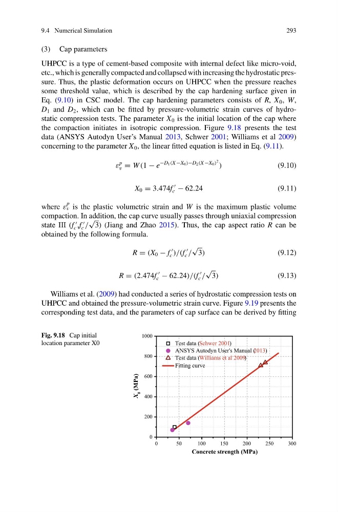
the compaction initiates in isotropic compression. Figure 9.18 presents the test
data (ANSYS Autodyn User’s Manual 2013, Schwer 2001; Williams et al 2009)
concerning to the parameter X 0 , the linear fitted equation is listed in Eq. (9.11).
ε
p
v = W (1 − e
−D 1 (X −X 0 )−D 2 (X −X 0 )
2 )
(9.10)
X 0 = 3.474f
c − 62.24
(9.11)
where ε
p
v is the plastic volumetric strain and W is the maximum plastic volume
compaction. In addition, the cap curve usually passes through uniaxial compression
state III (f
c ,f
c /
√
3) (Jiang and Zhao 2015). Thus, the cap aspect ratio R can be
obtained by the following formula.
R = (X 0 − f
c )/(f
c /
√
3)
(9.12)
R = (2.474f
c − 62.24)/(f
c /
√
3)
(9.13)
Williams et al. (2009) had conducted a series of hydrostatic compression tests on
UHPCC and obtained the pressure-volumetric strain curve. Figure 9.19 presents the
corresponding test data, and the parameters of cap surface can be derived by fitting
Fig. 9.18 Cap initial
location parameter X0
0
50
100
150
200
250
300
0
200
400
600
800
1000
X
0
(MPa)
Concrete strength (MPa)
Test data (Schwer 2001)
ANSYS Autodyn User's Manual ( 2013)
Test data (Williams et al 2009)
Fitting curve
293
(3) Cap parameters
UHPCC is a type of cement-based composite with internal defect like micro-void,
etc., which is generally compacted and collapsed with increasing the hydrostatic pressure. Thus, the plastic deformation occurs on UHPCC when the pressure reaches
some threshold value, which is described by the cap hardening surface given in
Eq. (9.10) in CSC model. The cap hardening parameters consists of R, X 0 , W,
D 1 and D 2 , which can be fitted by pressure-volumetric strain curves of hydrostatic compression tests. The parameter X 0 is the initial location of the cap where
the compaction initiates in isotropic compression. Figure 9.18 presents the test
data (ANSYS Autodyn User’s Manual 2013, Schwer 2001; Williams et al 2009)
concerning to the parameter X 0 , the linear fitted equation is listed in Eq. (9.11).
ε
p
v = W (1 − e
−D 1 (X −X 0 )−D 2 (X −X 0 )
2 )
(9.10)
X 0 = 3.474f
c − 62.24
(9.11)
where ε
p
v is the plastic volumetric strain and W is the maximum plastic volume
compaction. In addition, the cap curve usually passes through uniaxial compression
state III (f
c ,f
c /
√
3) (Jiang and Zhao 2015). Thus, the cap aspect ratio R can be
obtained by the following formula.
R = (X 0 − f
c )/(f
c /
√
3)
(9.12)
R = (2.474f
c − 62.24)/(f
c /
√
3)
(9.13)
Williams et al. (2009) had conducted a series of hydrostatic compression tests on
UHPCC and obtained the pressure-volumetric strain curve. Figure 9.19 presents the
corresponding test data, and the parameters of cap surface can be derived by fitting
Fig. 9.18 Cap initial
location parameter X0
0
50
100
150
200
250
300
0
200
400
600
800
1000
X
0
(MPa)
Concrete strength (MPa)
Test data (Schwer 2001)
ANSYS Autodyn User's Manual ( 2013)
Test data (Williams et al 2009)
Fitting curve