

290
9 Dynamic Responses of Reinforced UHPCC Members Under …
(1) Modulus parameters
The bulk modulus K and shear modulus G of UHPCC can be determined by the elastic
modulus E and Poisson’s ratio ν in Eq. (9.3). Generally, the Poisson’s ratio and elastic
modulus E are derived from the static compression test on prism specimens.
K =
E
3(1 − 2ν)
, G =
E
2(1 + ν)
(9.3)
(2) Strength parameters
The material strength in CSC model is controlled by the shear failure surface in the
tensile and low confining pressure regimes (Murray 2007). There are three meridians for shear failure surface, i.e., compression, tensile and torsion, which can be
determined by the triaxial compression test (TXC), triaxial tensile test (TXE) and
torsion test (TOR). The compression meridian given in Eq. (9.4) is the foundation for
defining the shear failure surface. Besides, the states on torsion and tensile meridians
can be converted from compression meridian by the Rubin scaling function . In
Eq. (9.5), Q 1 and Q 2 are the Rubin scaling factors for torsion and extension meridians, respectively. The strength on torsion and tensile meridians are modeled as Q 1 F f
and Q 2 F f , respectively. The compression meridian, tension meridian and the control
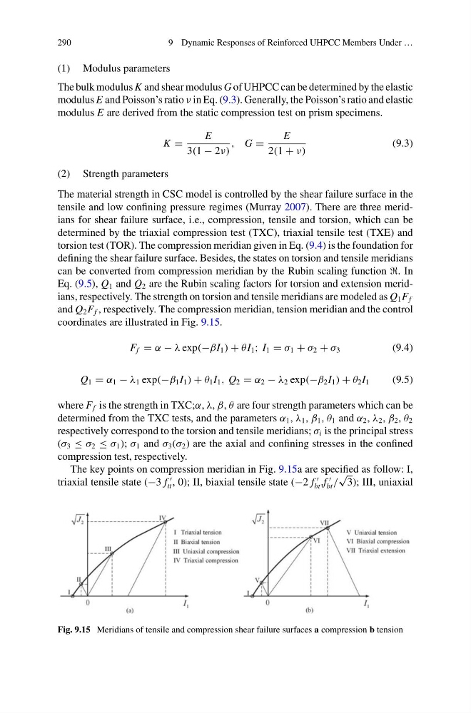
coordinates are illustrated in Fig. 9.15.
F f = α − λ exp(−βI 1 ) + θ I 1 ; I 1 = σ 1 + σ 2 + σ 3
(9.4)
Q 1 = α 1 − λ 1 exp(−β 1 I 1 ) + θ 1 I 1 , Q 2 = α 2 − λ 2 exp(−β 2 I 1 ) + θ 2 I 1
(9.5)
where F f is the strength in TXC;α, λ, β, θ are four strength parameters which can be
determined from the TXC tests, and the parameters α 1 , λ 1 , β 1 , θ 1 and α 2 , λ 2 , β 2 , θ 2
respectively correspond to the torsion and tensile meridians; σ i is the principal stress
(σ 3 ≤ σ 2 ≤ σ 1 ); σ 1 and σ 3 (σ 2 ) are the axial and confining stresses in the confined
compression test, respectively.
The key points on compression meridian in Fig. 9.15a are specified as follow: I,
triaxial tensile state (−3 f
tt , 0); II, biaxial tensile state (−2 f
bt ,f
bt /
√
3); III, uniaxial
Fig. 9.15 Meridians of tensile and compression shear failure surfaces a compression b tension
9 Dynamic Responses of Reinforced UHPCC Members Under …
(1) Modulus parameters
The bulk modulus K and shear modulus G of UHPCC can be determined by the elastic
modulus E and Poisson’s ratio ν in Eq. (9.3). Generally, the Poisson’s ratio and elastic
modulus E are derived from the static compression test on prism specimens.
K =
E
3(1 − 2ν)
, G =
E
2(1 + ν)
(9.3)
(2) Strength parameters
The material strength in CSC model is controlled by the shear failure surface in the
tensile and low confining pressure regimes (Murray 2007). There are three meridians for shear failure surface, i.e., compression, tensile and torsion, which can be
determined by the triaxial compression test (TXC), triaxial tensile test (TXE) and
torsion test (TOR). The compression meridian given in Eq. (9.4) is the foundation for
defining the shear failure surface. Besides, the states on torsion and tensile meridians
can be converted from compression meridian by the Rubin scaling function . In
Eq. (9.5), Q 1 and Q 2 are the Rubin scaling factors for torsion and extension meridians, respectively. The strength on torsion and tensile meridians are modeled as Q 1 F f
and Q 2 F f , respectively. The compression meridian, tension meridian and the control
coordinates are illustrated in Fig. 9.15.
F f = α − λ exp(−βI 1 ) + θ I 1 ; I 1 = σ 1 + σ 2 + σ 3
(9.4)
Q 1 = α 1 − λ 1 exp(−β 1 I 1 ) + θ 1 I 1 , Q 2 = α 2 − λ 2 exp(−β 2 I 1 ) + θ 2 I 1
(9.5)
where F f is the strength in TXC;α, λ, β, θ are four strength parameters which can be
determined from the TXC tests, and the parameters α 1 , λ 1 , β 1 , θ 1 and α 2 , λ 2 , β 2 , θ 2
respectively correspond to the torsion and tensile meridians; σ i is the principal stress
(σ 3 ≤ σ 2 ≤ σ 1 ); σ 1 and σ 3 (σ 2 ) are the axial and confining stresses in the confined
compression test, respectively.
The key points on compression meridian in Fig. 9.15a are specified as follow: I,
triaxial tensile state (−3 f
tt , 0); II, biaxial tensile state (−2 f
bt ,f
bt /
√
3); III, uniaxial
Fig. 9.15 Meridians of tensile and compression shear failure surfaces a compression b tension