

288
9 Dynamic Responses of Reinforced UHPCC Members Under …
9.4 Numerical Simulation
9.4.1 FE Model
To further study the impact resistance of specimens under low-velocity lateral impact,
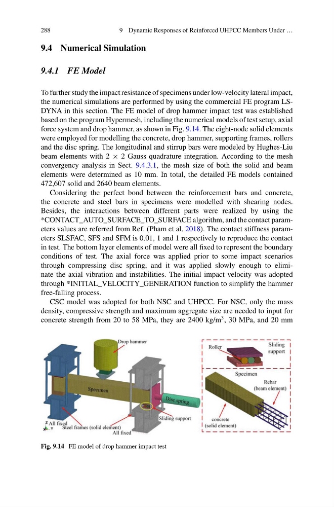
the numerical simulations are performed by using the commercial FE program LSDYNA in this section. The FE model of drop hammer impact test was established
based on the program Hypermesh, including the numerical models of test setup, axial
force system and drop hammer, as shown in Fig. 9.14. The eight-node solid elements
were employed for modelling the concrete, drop hammer, supporting frames, rollers
and the disc spring. The longitudinal and stirrup bars were modeled by Hughes-Liu
beam elements with 2 × 2 Gauss quadrature integration. According to the mesh
convergency analysis in Sect. 9.4.3.1, the mesh size of both the solid and beam
elements were determined as 10 mm. In total, the detailed FE models contained
472,607 solid and 2640 beam elements.
Considering the perfect bond between the reinforcement bars and concrete,
the concrete and steel bars in specimens were modelled with shearing nodes.
Besides, the interactions between different parts were realized by using the
*CONTACT_AUTO_SURFACE_TO_SURFACE algorithm, and the contact parameters values are referred from Ref. (Pham et al. 2018). The contact stiffness parameters SLSFAC, SFS and SFM is 0.01, 1 and 1 respectively to reproduce the contact
in test. The bottom layer elements of model were all fixed to represent the boundary
conditions of test. The axial force was applied prior to some impact scenarios
through compressing disc spring, and it was applied slowly enough to eliminate the axial vibration and instabilities. The initial impact velocity was adopted
through *INITIAL_VELOCITY_GENERATION function to simplify the hammer
free-falling process.
CSC model was adopted for both NSC and UHPCC. For NSC, only the mass
density, compressive strength and maximum aggregate size are needed to input for
concrete strength from 20 to 58 MPa, they are 2400 kg/m
3 , 30 MPa, and 20 mm
Fig. 9.14 FE model of drop hammer impact test
9 Dynamic Responses of Reinforced UHPCC Members Under …
9.4 Numerical Simulation
9.4.1 FE Model
To further study the impact resistance of specimens under low-velocity lateral impact,
the numerical simulations are performed by using the commercial FE program LSDYNA in this section. The FE model of drop hammer impact test was established
based on the program Hypermesh, including the numerical models of test setup, axial
force system and drop hammer, as shown in Fig. 9.14. The eight-node solid elements
were employed for modelling the concrete, drop hammer, supporting frames, rollers
and the disc spring. The longitudinal and stirrup bars were modeled by Hughes-Liu
beam elements with 2 × 2 Gauss quadrature integration. According to the mesh
convergency analysis in Sect. 9.4.3.1, the mesh size of both the solid and beam
elements were determined as 10 mm. In total, the detailed FE models contained
472,607 solid and 2640 beam elements.
Considering the perfect bond between the reinforcement bars and concrete,
the concrete and steel bars in specimens were modelled with shearing nodes.
Besides, the interactions between different parts were realized by using the
*CONTACT_AUTO_SURFACE_TO_SURFACE algorithm, and the contact parameters values are referred from Ref. (Pham et al. 2018). The contact stiffness parameters SLSFAC, SFS and SFM is 0.01, 1 and 1 respectively to reproduce the contact
in test. The bottom layer elements of model were all fixed to represent the boundary
conditions of test. The axial force was applied prior to some impact scenarios
through compressing disc spring, and it was applied slowly enough to eliminate the axial vibration and instabilities. The initial impact velocity was adopted
through *INITIAL_VELOCITY_GENERATION function to simplify the hammer
free-falling process.
CSC model was adopted for both NSC and UHPCC. For NSC, only the mass
density, compressive strength and maximum aggregate size are needed to input for
concrete strength from 20 to 58 MPa, they are 2400 kg/m
3 , 30 MPa, and 20 mm
Fig. 9.14 FE model of drop hammer impact test