

278
9 Dynamic Responses of Reinforced UHPCC Members Under …
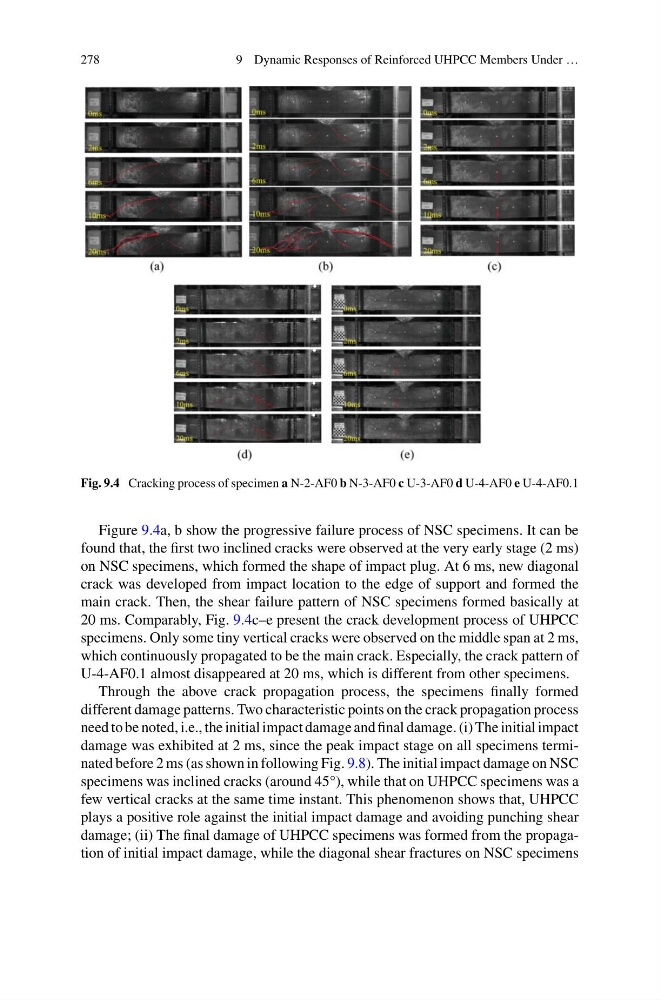
Fig. 9.4 Cracking process of specimen a N-2-AF0 b N-3-AF0 c U-3-AF0 d U-4-AF0 e U-4-AF0.1
Figure 9.4a, b show the progressive failure process of NSC specimens. It can be
found that, the first two inclined cracks were observed at the very early stage (2 ms)
on NSC specimens, which formed the shape of impact plug. At 6 ms, new diagonal
crack was developed from impact location to the edge of support and formed the
main crack. Then, the shear failure pattern of NSC specimens formed basically at
20 ms. Comparably, Fig. 9.4c–e present the crack development process of UHPCC
specimens. Only some tiny vertical cracks were observed on the middle span at 2 ms,
which continuously propagated to be the main crack. Especially, the crack pattern of
U-4-AF0.1 almost disappeared at 20 ms, which is different from other specimens.
Through the above crack propagation process, the specimens finally formed
different damage patterns. Two characteristic points on the crack propagation process
need to be noted, i.e., the initial impact damage and final damage. (i) The initial impact
damage was exhibited at 2 ms, since the peak impact stage on all specimens terminated before 2 ms (as shown in following Fig. 9.8). The initial impact damage on NSC
specimens was inclined cracks (around 45°), while that on UHPCC specimens was a
few vertical cracks at the same time instant. This phenomenon shows that, UHPCC
plays a positive role against the initial impact damage and avoiding punching shear
damage; (ii) The final damage of UHPCC specimens was formed from the propagation of initial impact damage, while the diagonal shear fractures on NSC specimens
9 Dynamic Responses of Reinforced UHPCC Members Under …
Fig. 9.4 Cracking process of specimen a N-2-AF0 b N-3-AF0 c U-3-AF0 d U-4-AF0 e U-4-AF0.1
Figure 9.4a, b show the progressive failure process of NSC specimens. It can be
found that, the first two inclined cracks were observed at the very early stage (2 ms)
on NSC specimens, which formed the shape of impact plug. At 6 ms, new diagonal
crack was developed from impact location to the edge of support and formed the
main crack. Then, the shear failure pattern of NSC specimens formed basically at
20 ms. Comparably, Fig. 9.4c–e present the crack development process of UHPCC
specimens. Only some tiny vertical cracks were observed on the middle span at 2 ms,
which continuously propagated to be the main crack. Especially, the crack pattern of
U-4-AF0.1 almost disappeared at 20 ms, which is different from other specimens.
Through the above crack propagation process, the specimens finally formed
different damage patterns. Two characteristic points on the crack propagation process
need to be noted, i.e., the initial impact damage and final damage. (i) The initial impact
damage was exhibited at 2 ms, since the peak impact stage on all specimens terminated before 2 ms (as shown in following Fig. 9.8). The initial impact damage on NSC
specimens was inclined cracks (around 45°), while that on UHPCC specimens was a
few vertical cracks at the same time instant. This phenomenon shows that, UHPCC
plays a positive role against the initial impact damage and avoiding punching shear
damage; (ii) The final damage of UHPCC specimens was formed from the propagation of initial impact damage, while the diagonal shear fractures on NSC specimens