

250
8 Response of UHPCC-FST Subjected to Low-Velocity Impact
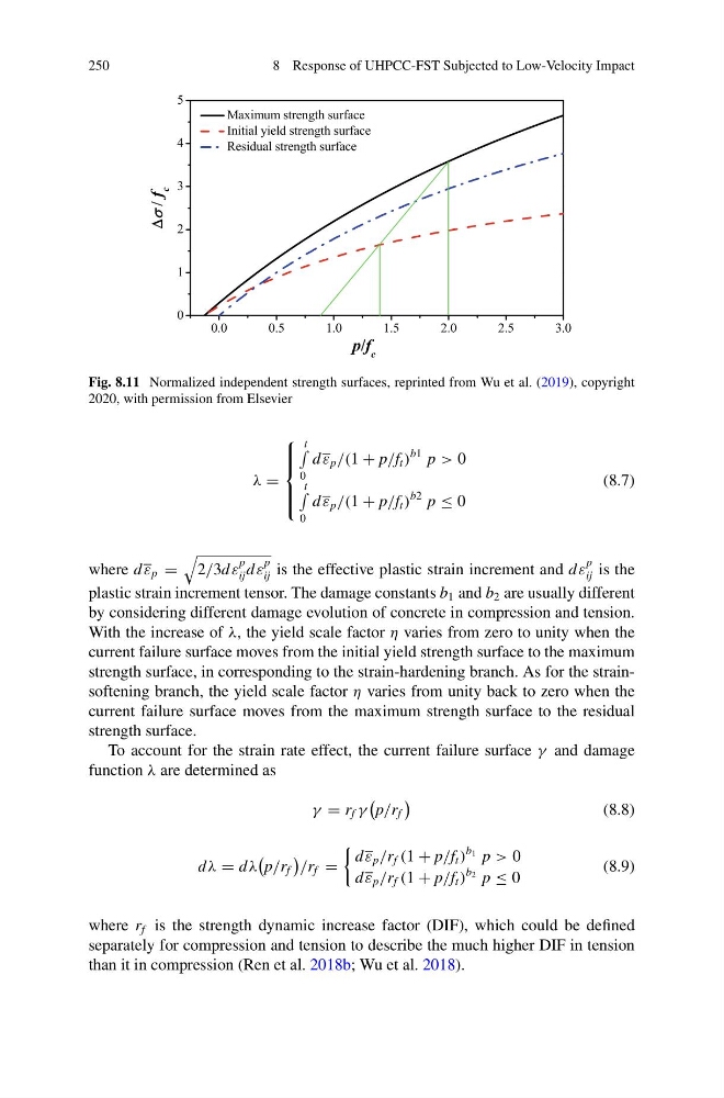
Fig. 8.11 Normalized independent strength surfaces, reprinted from Wu et al. (2019), copyright
2020, with permission from Elsevier
λ =
⎧
⎪ ⎪ ⎨
⎪ ⎪ ⎩
t
0
d ε p /(1 + p/f t )
b1 p > 0
t
0
d ε p /(1 + p/f t )
b2 p ≤ 0
(8.7)
where d ε p =
2/3d ε
p
ij d ε
p
ij is the effective plastic strain increment and d ε
p
ij is the
plastic strain increment tensor. The damage constants b 1 and b 2 are usually different
by considering different damage evolution of concrete in compression and tension.
With the increase of λ, the yield scale factor η varies from zero to unity when the
current failure surface moves from the initial yield strength surface to the maximum
strength surface, in corresponding to the strain-hardening branch. As for the strainsoftening branch, the yield scale factor η varies from unity back to zero when the
current failure surface moves from the maximum strength surface to the residual
strength surface.
To account for the strain rate effect, the current failure surface γ and damage
function λ are determined as
γ = r f γ
p/r f
(8.8)
d λ = d λ
p/r f
/r f =
d ε p /r f (1 + p/f t )
b 1 p > 0
d ε p /r f (1 + p/f t )
b 2 p ≤ 0
(8.9)
where r f is the strength dynamic increase factor (DIF), which could be defined
separately for compression and tension to describe the much higher DIF in tension
than it in compression (Ren et al. 2018b; Wu et al. 2018).
8 Response of UHPCC-FST Subjected to Low-Velocity Impact
Fig. 8.11 Normalized independent strength surfaces, reprinted from Wu et al. (2019), copyright
2020, with permission from Elsevier
λ =
⎧
⎪ ⎪ ⎨
⎪ ⎪ ⎩
t
0
d ε p /(1 + p/f t )
b1 p > 0
t
0
d ε p /(1 + p/f t )
b2 p ≤ 0
(8.7)
where d ε p =
2/3d ε
p
ij d ε
p
ij is the effective plastic strain increment and d ε
p
ij is the
plastic strain increment tensor. The damage constants b 1 and b 2 are usually different
by considering different damage evolution of concrete in compression and tension.
With the increase of λ, the yield scale factor η varies from zero to unity when the
current failure surface moves from the initial yield strength surface to the maximum
strength surface, in corresponding to the strain-hardening branch. As for the strainsoftening branch, the yield scale factor η varies from unity back to zero when the
current failure surface moves from the maximum strength surface to the residual
strength surface.
To account for the strain rate effect, the current failure surface γ and damage
function λ are determined as
γ = r f γ
p/r f
(8.8)
d λ = d λ
p/r f
/r f =
d ε p /r f (1 + p/f t )
b 1 p > 0
d ε p /r f (1 + p/f t )
b 2 p ≤ 0
(8.9)
where r f is the strength dynamic increase factor (DIF), which could be defined
separately for compression and tension to describe the much higher DIF in tension
than it in compression (Ren et al. 2018b; Wu et al. 2018).