

7.3 Impact Test on NP450 Armor Steel/UHPCC and NP500 Armor …
221
Projectile penetration into concrete target always forms the frustum-of-cone shaped
crater and is followed by a cylindrical tunnel with the diameter nearly equal to the
projectile shank diameter. The average front crater diameter d c of UHPCC target can
be derived by averaging the dimensions of crater surface from four directions, i.e.,
horizontal, vertical, 45° and 135°. The crater height H c , and the surface area A c are
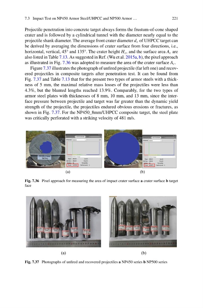
also listed in Table 7.13. As suggested in Ref. (Wu et al. 2015a, b), the pixel approach
as illustrated in Fig. 7.36 was adopted to measure the area of the crater surface A c .
Figure 7.37 illustrates the photograph of unfired projectile (far left one) and recovered projectiles in composite targets after penetration test. It can be found from
Fig. 7.37 and Table 7.13 that for the present two types of armor steels with a thickness of 5 mm, the maximal relative mass losses of the projectiles were less than
4.3%, but the blunted lengths reached 13.9%. Comparably, for the two types of
armor steel plates with thicknesses of 8 mm, 10 mm, and 13 mm, since the interface pressure between projectile and target was far greater than the dynamic yield
strength of the projectile, the projectiles endured obvious erosions or fractures, as
shown in Fig. 7.37. For the NP450_8mm/UHPCC composite target, the steel plate
was critically perforated with a striking velocity of 481 m/s.
Fig. 7.36 Pixel approach for measuring the area of impact crater surface a crater surface b target
face
Fig. 7.37 Photographs of unfired and recovered projectiles a NP450 series b NP500 series
221
Projectile penetration into concrete target always forms the frustum-of-cone shaped
crater and is followed by a cylindrical tunnel with the diameter nearly equal to the
projectile shank diameter. The average front crater diameter d c of UHPCC target can
be derived by averaging the dimensions of crater surface from four directions, i.e.,
horizontal, vertical, 45° and 135°. The crater height H c , and the surface area A c are
also listed in Table 7.13. As suggested in Ref. (Wu et al. 2015a, b), the pixel approach
as illustrated in Fig. 7.36 was adopted to measure the area of the crater surface A c .
Figure 7.37 illustrates the photograph of unfired projectile (far left one) and recovered projectiles in composite targets after penetration test. It can be found from
Fig. 7.37 and Table 7.13 that for the present two types of armor steels with a thickness of 5 mm, the maximal relative mass losses of the projectiles were less than
4.3%, but the blunted lengths reached 13.9%. Comparably, for the two types of
armor steel plates with thicknesses of 8 mm, 10 mm, and 13 mm, since the interface pressure between projectile and target was far greater than the dynamic yield
strength of the projectile, the projectiles endured obvious erosions or fractures, as
shown in Fig. 7.37. For the NP450_8mm/UHPCC composite target, the steel plate
was critically perforated with a striking velocity of 481 m/s.
Fig. 7.36 Pixel approach for measuring the area of impact crater surface a crater surface b target
face
Fig. 7.37 Photographs of unfired and recovered projectiles a NP450 series b NP500 series