

5.3 Corundum Aggregated UHPCC Target
125
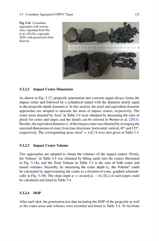
Fig. 5.16 Corundum
aggregates with various
sizes, reprinted from Wu
et al. (2015b), copyright
2020, with permission from
Elsevier
5.3.2.2 Impact Crater Dimension
As shown in Fig. 5.17, projectile penetration into concrete target always forms the
impact crater and followed by a cylindrical tunnel with the diameter nearly equal
to the projectile shank diameter d. In this section, the pixel and equivalent diameter
approaches are adopted to measure the areas of impact craters, respectively. The
crater areas denoted by Area
1 in Table 5.4 were obtained by measuring the ratio of
pixels for crater and target, and the details can be referred in Werner et al. (2013).
Besides, the equivalent diameter d c of the impact crater was obtained by averaging the
maximal dimensions of crater from four directions: horizontal, vertical, 45° and 135°,
respectively. The corresponding areas Area
2
= π d
2
c /4 were also given in Table 5.4.
5.3.2.3 Impact Crater Volume
Two approaches are adopted to obtain the volumes of the impact craters. Firstly,
the Volume
1 in Table 5.4 was obtained by filling sands into the craters illustrated
in Fig. 5.18a, and the Total Volume in Table 5.4 is the sum of both crater and
tunnel volumes. Secondly, by measuring the crater depth h c , the Volume
2 could
be calculated by approximating the crater as a frustum-of-cone, graphed schematically in Fig. 5.18b. The slope angle α = arctan[(d c − d)/2h c ] of each target could
be calculated and listed in Table 5.4.
5.3.2.4 DOP
After each shot, the penetration test data including the DOP of the projectile as well
as the crater areas and volumes were recorded and listed in Table 5.4. To facilitate
125
Fig. 5.16 Corundum
aggregates with various
sizes, reprinted from Wu
et al. (2015b), copyright
2020, with permission from
Elsevier
5.3.2.2 Impact Crater Dimension
As shown in Fig. 5.17, projectile penetration into concrete target always forms the
impact crater and followed by a cylindrical tunnel with the diameter nearly equal
to the projectile shank diameter d. In this section, the pixel and equivalent diameter
approaches are adopted to measure the areas of impact craters, respectively. The
crater areas denoted by Area
1 in Table 5.4 were obtained by measuring the ratio of
pixels for crater and target, and the details can be referred in Werner et al. (2013).
Besides, the equivalent diameter d c of the impact crater was obtained by averaging the
maximal dimensions of crater from four directions: horizontal, vertical, 45° and 135°,
respectively. The corresponding areas Area
2
= π d
2
c /4 were also given in Table 5.4.
5.3.2.3 Impact Crater Volume
Two approaches are adopted to obtain the volumes of the impact craters. Firstly,
the Volume
1 in Table 5.4 was obtained by filling sands into the craters illustrated
in Fig. 5.18a, and the Total Volume in Table 5.4 is the sum of both crater and
tunnel volumes. Secondly, by measuring the crater depth h c , the Volume
2 could
be calculated by approximating the crater as a frustum-of-cone, graphed schematically in Fig. 5.18b. The slope angle α = arctan[(d c − d)/2h c ] of each target could
be calculated and listed in Table 5.4.
5.3.2.4 DOP
After each shot, the penetration test data including the DOP of the projectile as well
as the crater areas and volumes were recorded and listed in Table 5.4. To facilitate