

116
5 Projectile Penetrations into Coarse Aggregated UHPCC Targets
(a)
(b)
(c)
(d)
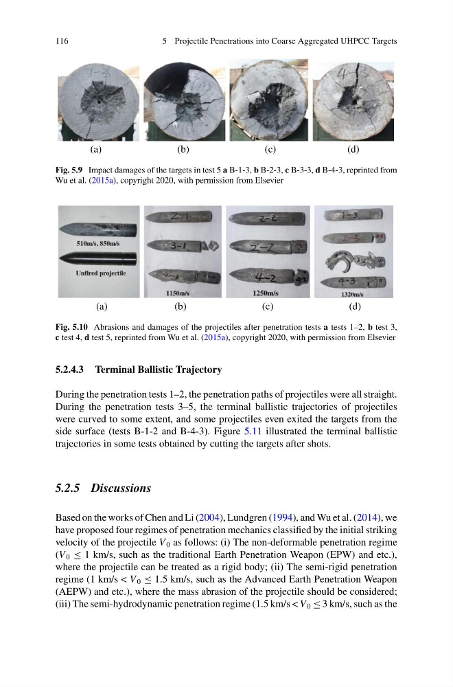
Fig. 5.9 Impact damages of the targets in test 5 a B-1-3, b B-2-3, c B-3-3, d B-4-3, reprinted from
Wu et al. (2015a), copyright 2020, with permission from Elsevier
(a)
(b)
(c)
(d)
Fig. 5.10 Abrasions and damages of the projectiles after penetration tests a tests 1–2, b test 3,
c test 4, d test 5, reprinted from Wu et al. (2015a), copyright 2020, with permission from Elsevier
5.2.4.3 Terminal Ballistic Trajectory
During the penetration tests 1–2, the penetration paths of projectiles were all straight.
During the penetration tests 3–5, the terminal ballistic trajectories of projectiles
were curved to some extent, and some projectiles even exited the targets from the
side surface (tests B-1-2 and B-4-3). Figure 5.11 illustrated the terminal ballistic
trajectories in some tests obtained by cutting the targets after shots.
5.2.5 Discussions
Based on the works of Chen and Li (2004), Lundgren (1994), and Wu et al. (2014), we
have proposed four regimes of penetration mechanics classified by the initial striking
velocity of the projectile V 0 as follows: (i) The non-deformable penetration regime
(V 0 ≤ 1 km/s, such as the traditional Earth Penetration Weapon (EPW) and etc.),
where the projectile can be treated as a rigid body; (ii) The semi-rigid penetration
regime (1 km/s < V 0 ≤ 1.5 km/s, such as the Advanced Earth Penetration Weapon
(AEPW) and etc.), where the mass abrasion of the projectile should be considered;
(iii) The semi-hydrodynamic penetration regime (1.5 km/s < V 0 ≤ 3 km/s, such as the
5 Projectile Penetrations into Coarse Aggregated UHPCC Targets
(a)
(b)
(c)
(d)
Fig. 5.9 Impact damages of the targets in test 5 a B-1-3, b B-2-3, c B-3-3, d B-4-3, reprinted from
Wu et al. (2015a), copyright 2020, with permission from Elsevier
(a)
(b)
(c)
(d)
Fig. 5.10 Abrasions and damages of the projectiles after penetration tests a tests 1–2, b test 3,
c test 4, d test 5, reprinted from Wu et al. (2015a), copyright 2020, with permission from Elsevier
5.2.4.3 Terminal Ballistic Trajectory
During the penetration tests 1–2, the penetration paths of projectiles were all straight.
During the penetration tests 3–5, the terminal ballistic trajectories of projectiles
were curved to some extent, and some projectiles even exited the targets from the
side surface (tests B-1-2 and B-4-3). Figure 5.11 illustrated the terminal ballistic
trajectories in some tests obtained by cutting the targets after shots.
5.2.5 Discussions
Based on the works of Chen and Li (2004), Lundgren (1994), and Wu et al. (2014), we
have proposed four regimes of penetration mechanics classified by the initial striking
velocity of the projectile V 0 as follows: (i) The non-deformable penetration regime
(V 0 ≤ 1 km/s, such as the traditional Earth Penetration Weapon (EPW) and etc.),
where the projectile can be treated as a rigid body; (ii) The semi-rigid penetration
regime (1 km/s < V 0 ≤ 1.5 km/s, such as the Advanced Earth Penetration Weapon
(AEPW) and etc.), where the mass abrasion of the projectile should be considered;
(iii) The semi-hydrodynamic penetration regime (1.5 km/s < V 0 ≤ 3 km/s, such as the