

9.7 Size-Dependent Euler-Bernoulli Beams with Topologically Optimized Microstructure 379
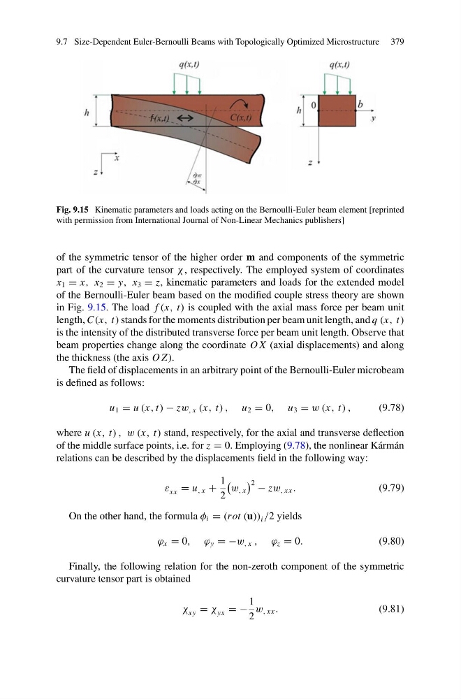
Fig. 9.15 Kinematic parameters and loads acting on the Bernoulli-Euler beam element [reprinted
with permission from International Journal of Non-Linear Mechanics publishers]
of the symmetric tensor of the higher order m and components of the symmetric
part of the curvature tensor χ , respectively. The employed system of coordinates
x 1 = x, x 2 = y, x 3 = z, kinematic parameters and loads for the extended model
of the Bernoulli-Euler beam based on the modified couple stress theory are shown
in Fig. 9.15. The load f (x, t) is coupled with the axial mass force per beam unit
length, C(x, t) stands for the moments distribution per beam unit length, and q (x, t)
is the intensity of the distributed transverse force per beam unit length. Observe that
beam properties change along the coordinate O X (axial displacements) and along
the thickness (the axis O Z).
The field of displacements in an arbitrary point of the Bernoulli-Euler microbeam
is defined as follows:
u 1 = u (x, t) − zw , x (x, t) , u 2 = 0, u 3 = w (x, t) ,
(9.78)
where u (x, t) , w (x, t) stand, respectively, for the axial and transverse deflection
of the middle surface points, i.e. for z = 0. Employing (9.78), the nonlinear Kármán
relations can be described by the displacements field in the following way:
ε xx = u , x +
1
2
w , x
2 − zw , xx .
(9.79)
On the other hand, the formula φ i = (rot (u)) i /2 yields
ϕ x = 0, ϕ y = −w , x , ϕ z = 0.
(9.80)
Finally, the following relation for the non-zeroth component of the symmetric
curvature tensor part is obtained
χ xy = χ yx = −
1
2
w , xx .
(9.81)
Fig. 9.15 Kinematic parameters and loads acting on the Bernoulli-Euler beam element [reprinted
with permission from International Journal of Non-Linear Mechanics publishers]
of the symmetric tensor of the higher order m and components of the symmetric
part of the curvature tensor χ , respectively. The employed system of coordinates
x 1 = x, x 2 = y, x 3 = z, kinematic parameters and loads for the extended model
of the Bernoulli-Euler beam based on the modified couple stress theory are shown
in Fig. 9.15. The load f (x, t) is coupled with the axial mass force per beam unit
length, C(x, t) stands for the moments distribution per beam unit length, and q (x, t)
is the intensity of the distributed transverse force per beam unit length. Observe that
beam properties change along the coordinate O X (axial displacements) and along
the thickness (the axis O Z).
The field of displacements in an arbitrary point of the Bernoulli-Euler microbeam
is defined as follows:
u 1 = u (x, t) − zw , x (x, t) , u 2 = 0, u 3 = w (x, t) ,
(9.78)
where u (x, t) , w (x, t) stand, respectively, for the axial and transverse deflection
of the middle surface points, i.e. for z = 0. Employing (9.78), the nonlinear Kármán
relations can be described by the displacements field in the following way:
ε xx = u , x +
1
2
w , x
2 − zw , xx .
(9.79)
On the other hand, the formula φ i = (rot (u)) i /2 yields
ϕ x = 0, ϕ y = −w , x , ϕ z = 0.
(9.80)
Finally, the following relation for the non-zeroth component of the symmetric
curvature tensor part is obtained
χ xy = χ yx = −
1
2
w , xx .
(9.81)