

7.4 Chaotic Dynamics of Size-Dependent Graded Timoshenko Beams
213
where σ i j , ε i j , m i j , and χ i j denote components the Cauchy stress tensor σ, the strain
tensor ε, the deviator part of the couple stress tensor m and the symmetric curvature
tensor χ , respectively. In addition, u i are components of the displacement vector and
u, θ stand for the infinitely small vector of rotation with components θ i . Observe that
θ i = (rot (u)) i /2 . Two Lamé constants are denoted by λ and μ, whereas l stands
for the internal material length scale parameter.
It should be mentioned that the introduced theoretical background regarding the
internal material length scale parameter l has been experimentally validated for many
materials [15, 102, 107, 108].
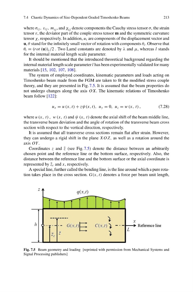
The system of employed coordinates, kinematic parameters and loads acting on
Timoshenko beam made from the FGM are taken to fit the modified stress couple
theory, and they are presented in Fig. 7.5. It is assumed that the beam properties do
not undergo changes along the axis O X. The kinematic relations of Timoshenko
beam follow [122]:
u x = u (x, t) + zψ(x, t), u y = 0, u z = w (x, t) ,
(7.28)
where u (x, t) , w (x, t) and ψ (x, t) denote the axial shift of the beam middle line,
the transverse beam deviation and the angle of rotation of the transverse beam cross
section with respect to the vertical direction, respectively.
It is assumed that all transverse cross sections remain flat after strain. However,
they can undergo a rigid shift in the plane X O Z, as well as a rotation around the
axis OY .
Coordinates z and ˜
z (see Fig. 7.5) denote the distance between an arbitrarily
chosen point and the reference line or the bottom surface, respectively. Also, the
distance between the reference line and the bottom surface or the axial coordinate is
represented by ˜
z c and x, respectively.
A special line, further called the bending line, is the line around which a pure rotation takes place in the cross section. G(x, t) denotes a force per beam unit length,
Fig. 7.5 Beam geometry and loading [reprinted with permission from Mechanical Systems and
Signal Processing publishers]
213
where σ i j , ε i j , m i j , and χ i j denote components the Cauchy stress tensor σ, the strain
tensor ε, the deviator part of the couple stress tensor m and the symmetric curvature
tensor χ , respectively. In addition, u i are components of the displacement vector and
u, θ stand for the infinitely small vector of rotation with components θ i . Observe that
θ i = (rot (u)) i /2 . Two Lamé constants are denoted by λ and μ, whereas l stands
for the internal material length scale parameter.
It should be mentioned that the introduced theoretical background regarding the
internal material length scale parameter l has been experimentally validated for many
materials [15, 102, 107, 108].
The system of employed coordinates, kinematic parameters and loads acting on
Timoshenko beam made from the FGM are taken to fit the modified stress couple
theory, and they are presented in Fig. 7.5. It is assumed that the beam properties do
not undergo changes along the axis O X. The kinematic relations of Timoshenko
beam follow [122]:
u x = u (x, t) + zψ(x, t), u y = 0, u z = w (x, t) ,
(7.28)
where u (x, t) , w (x, t) and ψ (x, t) denote the axial shift of the beam middle line,
the transverse beam deviation and the angle of rotation of the transverse beam cross
section with respect to the vertical direction, respectively.
It is assumed that all transverse cross sections remain flat after strain. However,
they can undergo a rigid shift in the plane X O Z, as well as a rotation around the
axis OY .
Coordinates z and ˜
z (see Fig. 7.5) denote the distance between an arbitrarily
chosen point and the reference line or the bottom surface, respectively. Also, the
distance between the reference line and the bottom surface or the axial coordinate is
represented by ˜
z c and x, respectively.
A special line, further called the bending line, is the line around which a pure rotation takes place in the cross section. G(x, t) denotes a force per beam unit length,
Fig. 7.5 Beam geometry and loading [reprinted with permission from Mechanical Systems and
Signal Processing publishers]