

504
S. K. Sinha et al.
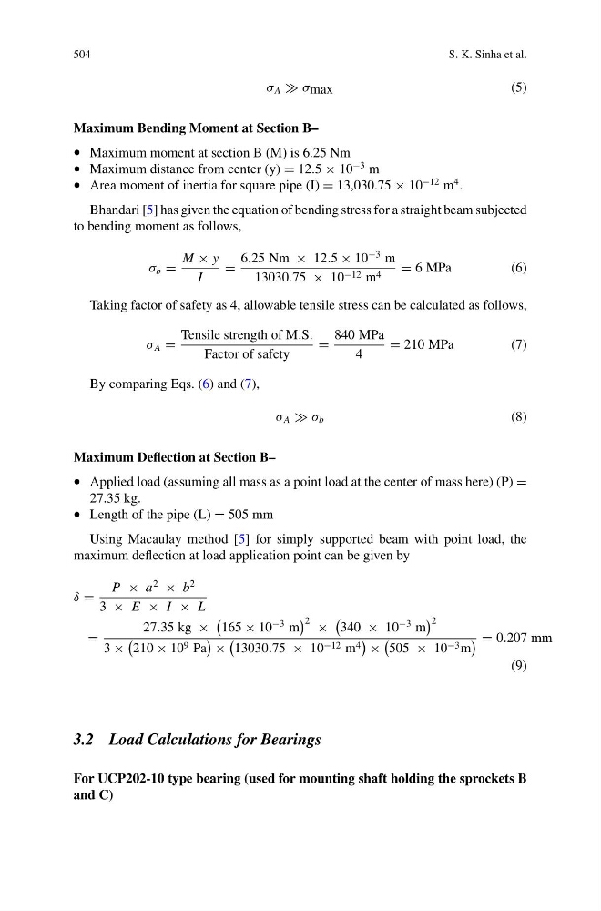
σ A σ max
(5)
Maximum Bending Moment at Section B–
• Maximum moment at section B (M) is 6.25 Nm
• Maximum distance from center (y) = 12.5 × 10
−3 m
• Area moment of inertia for square pipe (I) = 13,030.75 × 10
−12 m
4 .
Bhandari [5] has given the equation of bending stress for a straight beam subjected
to bending moment as follows,
σ b =
M × y
I
=
6.25 Nm × 12.5 × 10
−3 m
13030.75 × 10 −12 m 4 = 6 MPa
(6)
Taking factor of safety as 4, allowable tensile stress can be calculated as follows,
σ A =
Tensile strength of M.S.
Factor of safety
=
840 MPa
4
= 210 MPa
(7)
By comparing Eqs. (6) and (7),
σ A σ b
(8)
Maximum Deflection at Section B–
• Applied load (assuming all mass as a point load at the center of mass here) (P) =
27.35 kg.
• Length of the pipe (L) = 505 mm
Using Macaulay method [5] for simply supported beam with point load, the
maximum deflection at load application point can be given by
δ =
P × a
2
× b
2
3 × E × I × L
=
27.35 kg ×
165 × 10
−3 m
2 ×
340 × 10
−3 m
2
3 ×
210 × 10 9 Pa
×
13030.75 × 10 −12 m 4
×
505 × 10 −3 m
= 0.207 mm
(9)
3.2 Load Calculations for Bearings
For UCP202-10 type bearing (used for mounting shaft holding the sprockets B
and C)
S. K. Sinha et al.
σ A σ max
(5)
Maximum Bending Moment at Section B–
• Maximum moment at section B (M) is 6.25 Nm
• Maximum distance from center (y) = 12.5 × 10
−3 m
• Area moment of inertia for square pipe (I) = 13,030.75 × 10
−12 m
4 .
Bhandari [5] has given the equation of bending stress for a straight beam subjected
to bending moment as follows,
σ b =
M × y
I
=
6.25 Nm × 12.5 × 10
−3 m
13030.75 × 10 −12 m 4 = 6 MPa
(6)
Taking factor of safety as 4, allowable tensile stress can be calculated as follows,
σ A =
Tensile strength of M.S.
Factor of safety
=
840 MPa
4
= 210 MPa
(7)
By comparing Eqs. (6) and (7),
σ A σ b
(8)
Maximum Deflection at Section B–
• Applied load (assuming all mass as a point load at the center of mass here) (P) =
27.35 kg.
• Length of the pipe (L) = 505 mm
Using Macaulay method [5] for simply supported beam with point load, the
maximum deflection at load application point can be given by
δ =
P × a
2
× b
2
3 × E × I × L
=
27.35 kg ×
165 × 10
−3 m
2 ×
340 × 10
−3 m
2
3 ×
210 × 10 9 Pa
×
13030.75 × 10 −12 m 4
×
505 × 10 −3 m
= 0.207 mm
(9)
3.2 Load Calculations for Bearings
For UCP202-10 type bearing (used for mounting shaft holding the sprockets B
and C)