

Design of Automatic Multipurpose Indian Flatbread Maker
503
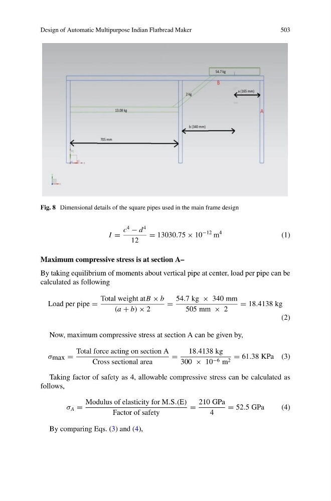
Fig. 8 Dimensional details of the square pipes used in the main frame design
I =
c
4
− d
4
12
= 13030.75 × 10
−12 m
4
(1)
Maximum compressive stress is at section A–
By taking equilibrium of moments about vertical pipe at center, load per pipe can be
calculated as following
Load per pipe =
Total weight atB × b
(a + b) × 2
=
54.7 kg × 340 mm
505 mm × 2
= 18.4138 kg
(2)
Now, maximum compressive stress at section A can be given by,
σ max =
Total force acting on section A
Cross sectional area
=
18.4138 kg
300 × 10 −6 m 2 = 61.38 KPa (3)
Taking factor of safety as 4, allowable compressive stress can be calculated as
follows,
σ A =
Modulus of elasticity for M.S.(E)
Factor of safety
=
210 GPa
4
= 52.5 GPa
(4)
By comparing Eqs. (3) and (4),
503
Fig. 8 Dimensional details of the square pipes used in the main frame design
I =
c
4
− d
4
12
= 13030.75 × 10
−12 m
4
(1)
Maximum compressive stress is at section A–
By taking equilibrium of moments about vertical pipe at center, load per pipe can be
calculated as following
Load per pipe =
Total weight atB × b
(a + b) × 2
=
54.7 kg × 340 mm
505 mm × 2
= 18.4138 kg
(2)
Now, maximum compressive stress at section A can be given by,
σ max =
Total force acting on section A
Cross sectional area
=
18.4138 kg
300 × 10 −6 m 2 = 61.38 KPa (3)
Taking factor of safety as 4, allowable compressive stress can be calculated as
follows,
σ A =
Modulus of elasticity for M.S.(E)
Factor of safety
=
210 GPa
4
= 52.5 GPa
(4)
By comparing Eqs. (3) and (4),