

480
A. Talli and A. C. Giriyapur
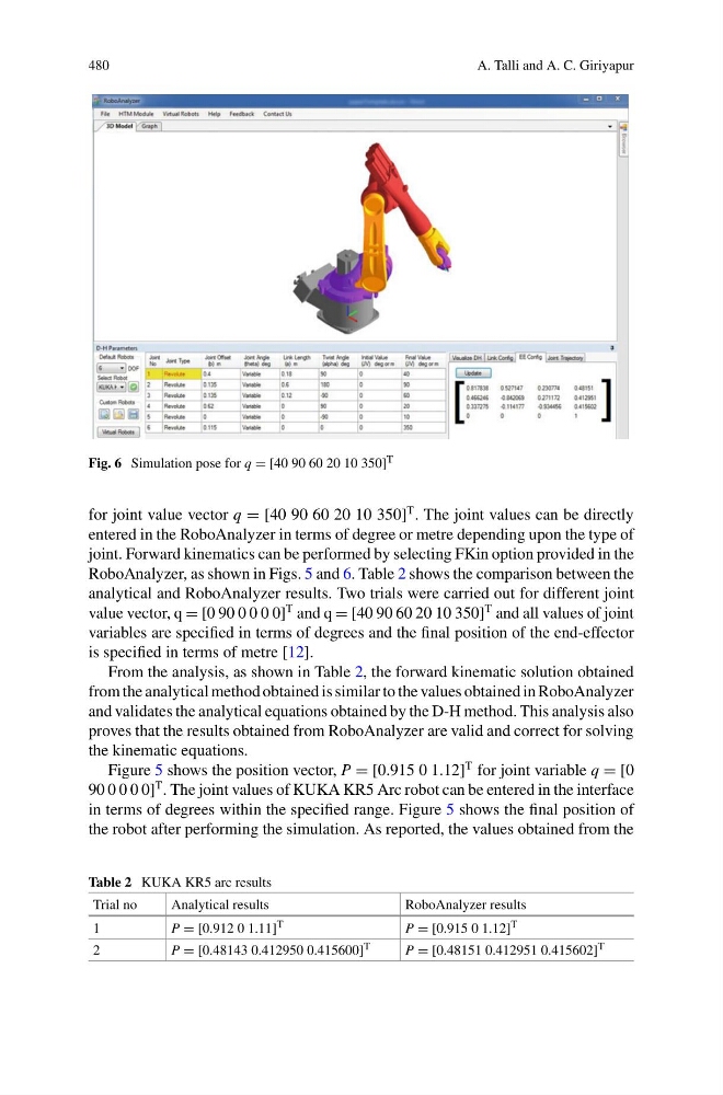
Fig. 6 Simulation pose for q = [40 90 60 20 10 350] T
for joint value vector q = [40 90 60 20 10 350]
T . The joint values can be directly
entered in the RoboAnalyzer in terms of degree or metre depending upon the type of
joint. Forward kinematics can be performed by selecting FKin option provided in the
RoboAnalyzer, as shown in Figs. 5 and 6. Table 2 shows the comparison between the
analytical and RoboAnalyzer results. Two trials were carried out for different joint
value vector, q = [0 90 0 0 0 0]
T and q = [40 90 60 20 10 350]
T and all values of joint
variables are specified in terms of degrees and the final position of the end-effector
is specified in terms of metre [12].
From the analysis, as shown in Table 2, the forward kinematic solution obtained
from the analytical method obtained is similar to the values obtained in RoboAnalyzer
and validates the analytical equations obtained by the D-H method. This analysis also
proves that the results obtained from RoboAnalyzer are valid and correct for solving
the kinematic equations.
Figure 5 shows the position vector, P = [0.915 0 1.12]
T for joint variable q = [0
90 0 0 0 0]
T . The joint values of KUKA KR5 Arc robot can be entered in the interface
in terms of degrees within the specified range. Figure 5 shows the final position of
the robot after performing the simulation. As reported, the values obtained from the
Table 2 KUKA KR5 arc results
Trial no
Analytical results
RoboAnalyzer results
1
P = [0.912 0 1.11] T
P = [0.915 0 1.12] T
2
P = [0.48143 0.412950 0.415600] T
P = [0.48151 0.412951 0.415602] T
A. Talli and A. C. Giriyapur
Fig. 6 Simulation pose for q = [40 90 60 20 10 350] T
for joint value vector q = [40 90 60 20 10 350]
T . The joint values can be directly
entered in the RoboAnalyzer in terms of degree or metre depending upon the type of
joint. Forward kinematics can be performed by selecting FKin option provided in the
RoboAnalyzer, as shown in Figs. 5 and 6. Table 2 shows the comparison between the
analytical and RoboAnalyzer results. Two trials were carried out for different joint
value vector, q = [0 90 0 0 0 0]
T and q = [40 90 60 20 10 350]
T and all values of joint
variables are specified in terms of degrees and the final position of the end-effector
is specified in terms of metre [12].
From the analysis, as shown in Table 2, the forward kinematic solution obtained
from the analytical method obtained is similar to the values obtained in RoboAnalyzer
and validates the analytical equations obtained by the D-H method. This analysis also
proves that the results obtained from RoboAnalyzer are valid and correct for solving
the kinematic equations.
Figure 5 shows the position vector, P = [0.915 0 1.12]
T for joint variable q = [0
90 0 0 0 0]
T . The joint values of KUKA KR5 Arc robot can be entered in the interface
in terms of degrees within the specified range. Figure 5 shows the final position of
the robot after performing the simulation. As reported, the values obtained from the
Table 2 KUKA KR5 arc results
Trial no
Analytical results
RoboAnalyzer results
1
P = [0.912 0 1.11] T
P = [0.915 0 1.12] T
2
P = [0.48143 0.412950 0.415600] T
P = [0.48151 0.412951 0.415602] T