

450
R. Sharma and V. Tanna
(d) Maximum bending moment acting of pipe from the shear force and bending
moment diagram.
(e) Central pipe of selected dimension was checked for maximum capacity of load
bearing that can carry to know the condition of failure.
(g) Checking for thickness of centre pipe of IS 3589 mild steel, yield stress =
310 MPa, E = 201 GPa, acceptable deflection d = L/240 = 12,000/240 = 50 mm by
taking maximum weight of 300 kg acting on the pipe. Since 8 inch, 8 mm thickness
central pipe have sufficient moment of inertia to resist bending, it is optimized and
preferred to select.
(h) By applying maximum moment of 3 kNm acting at 3 m distance, length of pipe
L = 12 m. By shear force and bending moment diagram, maximum moment of 12
kNm acts at the base portion, bending stress = 12 × 100 × 1000/Section modulus
230,369.2 = 52.0 MPa from Eq. 1.
(i) Since the stair case is fixed with bridge platform at the top, the central pipe is
considered simply supported. Here, A = 12 × 0.2032 = 2.4384 m
2 , wind pressure
P = 0.613 × (V
2 ) N/m
2 , where V = speed of wind = 35 m/s, P = 750.9 N/m
2 [4].
Drag coefficient for long cylindrical tube is taken 1.2. Therefore, Max. Wind force
F (or W ) = 2.19 kN calculated from Eq. 6 (maximum design force of 3 kN). By
shear force and bending moment diagram, maximum moment of 54 kNm acts at
the base portion, bending stress = 54 × 100 × 1000/Section modulus 230,369.2 =
234.0 MPa < 248 MPa of permissible bending stress of material from Eq. 5, hence
the structure is safe.
5.3 Tread Design Method and Calculation
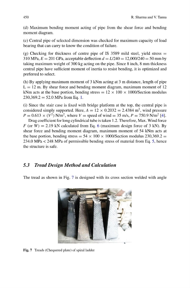
The tread as shown in Fig. 7 is designed with its cross section welded with angle
Fig. 7 Treads (Chequered plate) of spiral ladder
R. Sharma and V. Tanna
(d) Maximum bending moment acting of pipe from the shear force and bending
moment diagram.
(e) Central pipe of selected dimension was checked for maximum capacity of load
bearing that can carry to know the condition of failure.
(g) Checking for thickness of centre pipe of IS 3589 mild steel, yield stress =
310 MPa, E = 201 GPa, acceptable deflection d = L/240 = 12,000/240 = 50 mm by
taking maximum weight of 300 kg acting on the pipe. Since 8 inch, 8 mm thickness
central pipe have sufficient moment of inertia to resist bending, it is optimized and
preferred to select.
(h) By applying maximum moment of 3 kNm acting at 3 m distance, length of pipe
L = 12 m. By shear force and bending moment diagram, maximum moment of 12
kNm acts at the base portion, bending stress = 12 × 100 × 1000/Section modulus
230,369.2 = 52.0 MPa from Eq. 1.
(i) Since the stair case is fixed with bridge platform at the top, the central pipe is
considered simply supported. Here, A = 12 × 0.2032 = 2.4384 m
2 , wind pressure
P = 0.613 × (V
2 ) N/m
2 , where V = speed of wind = 35 m/s, P = 750.9 N/m
2 [4].
Drag coefficient for long cylindrical tube is taken 1.2. Therefore, Max. Wind force
F (or W ) = 2.19 kN calculated from Eq. 6 (maximum design force of 3 kN). By
shear force and bending moment diagram, maximum moment of 54 kNm acts at
the base portion, bending stress = 54 × 100 × 1000/Section modulus 230,369.2 =
234.0 MPa < 248 MPa of permissible bending stress of material from Eq. 5, hence
the structure is safe.
5.3 Tread Design Method and Calculation
The tread as shown in Fig. 7 is designed with its cross section welded with angle
Fig. 7 Treads (Chequered plate) of spiral ladder