

Structural Analysis, Design, and Implementation of Safety …
451
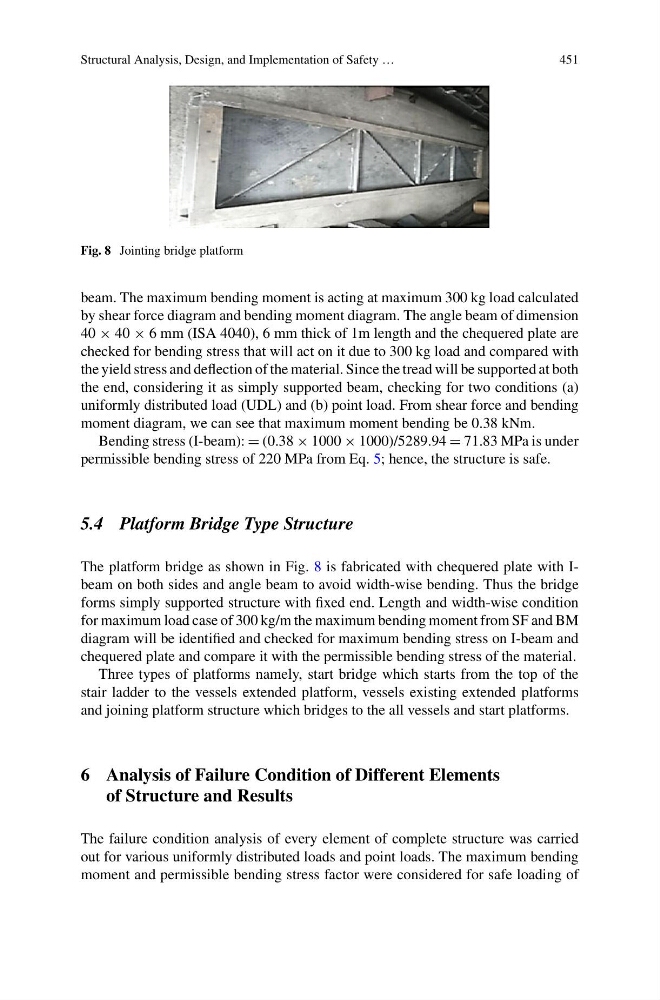
Fig. 8 Jointing bridge platform
beam. The maximum bending moment is acting at maximum 300 kg load calculated
by shear force diagram and bending moment diagram. The angle beam of dimension
40 × 40 × 6 mm (ISA 4040), 6 mm thick of 1m length and the chequered plate are
checked for bending stress that will act on it due to 300 kg load and compared with
the yield stress and deflection of the material. Since the tread will be supported at both
the end, considering it as simply supported beam, checking for two conditions (a)
uniformly distributed load (UDL) and (b) point load. From shear force and bending
moment diagram, we can see that maximum moment bending be 0.38 kNm.
Bending stress (I-beam): = (0.38 × 1000 × 1000)/5289.94 = 71.83 MPa is under
permissible bending stress of 220 MPa from Eq. 5; hence, the structure is safe.
5.4 Platform Bridge Type Structure
The platform bridge as shown in Fig. 8 is fabricated with chequered plate with Ibeam on both sides and angle beam to avoid width-wise bending. Thus the bridge
forms simply supported structure with fixed end. Length and width-wise condition
for maximum load case of 300 kg/m the maximum bending moment from SF and BM
diagram will be identified and checked for maximum bending stress on I-beam and
chequered plate and compare it with the permissible bending stress of the material.
Three types of platforms namely, start bridge which starts from the top of the
stair ladder to the vessels extended platform, vessels existing extended platforms
and joining platform structure which bridges to the all vessels and start platforms.
6 Analysis of Failure Condition of Different Elements
of Structure and Results
The failure condition analysis of every element of complete structure was carried
out for various uniformly distributed loads and point loads. The maximum bending
moment and permissible bending stress factor were considered for safe loading of
451
Fig. 8 Jointing bridge platform
beam. The maximum bending moment is acting at maximum 300 kg load calculated
by shear force diagram and bending moment diagram. The angle beam of dimension
40 × 40 × 6 mm (ISA 4040), 6 mm thick of 1m length and the chequered plate are
checked for bending stress that will act on it due to 300 kg load and compared with
the yield stress and deflection of the material. Since the tread will be supported at both
the end, considering it as simply supported beam, checking for two conditions (a)
uniformly distributed load (UDL) and (b) point load. From shear force and bending
moment diagram, we can see that maximum moment bending be 0.38 kNm.
Bending stress (I-beam): = (0.38 × 1000 × 1000)/5289.94 = 71.83 MPa is under
permissible bending stress of 220 MPa from Eq. 5; hence, the structure is safe.
5.4 Platform Bridge Type Structure
The platform bridge as shown in Fig. 8 is fabricated with chequered plate with Ibeam on both sides and angle beam to avoid width-wise bending. Thus the bridge
forms simply supported structure with fixed end. Length and width-wise condition
for maximum load case of 300 kg/m the maximum bending moment from SF and BM
diagram will be identified and checked for maximum bending stress on I-beam and
chequered plate and compare it with the permissible bending stress of the material.
Three types of platforms namely, start bridge which starts from the top of the
stair ladder to the vessels extended platform, vessels existing extended platforms
and joining platform structure which bridges to the all vessels and start platforms.
6 Analysis of Failure Condition of Different Elements
of Structure and Results
The failure condition analysis of every element of complete structure was carried
out for various uniformly distributed loads and point loads. The maximum bending
moment and permissible bending stress factor were considered for safe loading of