

Structural Analysis, Design, and Implementation of Safety …
449
Wind force F = A × P × cd,
(6)
[4] where, A = Projected area, P = Wind pressure, cd = Drag coefficient, and UDL
(Uniformly distributed load acting on central pipe).
5.1 Spiral Ladder
As per the vessels height the stair head room were optimized to 12 m and 2 m
diameter. The length of tread is 1 m which is sufficient of human to stand and width
is about 260 mm as per standard 2 × H + B = 540 to 680. The total number of steps
is optimized to 60 by applying the standard height between treads which is 200 mm.
5.2 Central Pipe
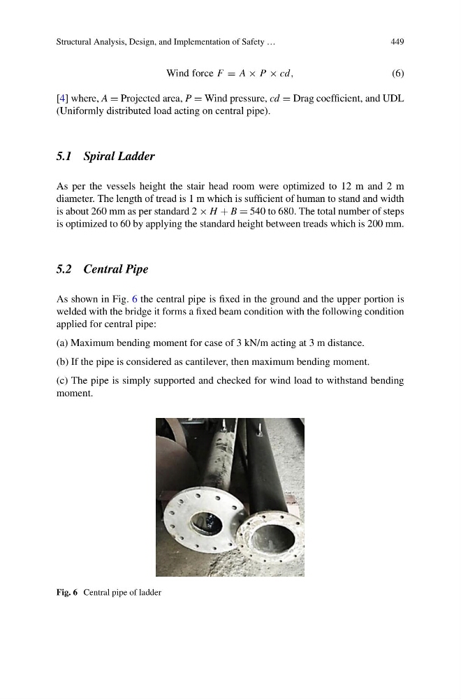
As shown in Fig. 6 the central pipe is fixed in the ground and the upper portion is
welded with the bridge it forms a fixed beam condition with the following condition
applied for central pipe:
(a) Maximum bending moment for case of 3 kN/m acting at 3 m distance.
(b) If the pipe is considered as cantilever, then maximum bending moment.
(c) The pipe is simply supported and checked for wind load to withstand bending
moment.
Fig. 6 Central pipe of ladder
449
Wind force F = A × P × cd,
(6)
[4] where, A = Projected area, P = Wind pressure, cd = Drag coefficient, and UDL
(Uniformly distributed load acting on central pipe).
5.1 Spiral Ladder
As per the vessels height the stair head room were optimized to 12 m and 2 m
diameter. The length of tread is 1 m which is sufficient of human to stand and width
is about 260 mm as per standard 2 × H + B = 540 to 680. The total number of steps
is optimized to 60 by applying the standard height between treads which is 200 mm.
5.2 Central Pipe
As shown in Fig. 6 the central pipe is fixed in the ground and the upper portion is
welded with the bridge it forms a fixed beam condition with the following condition
applied for central pipe:
(a) Maximum bending moment for case of 3 kN/m acting at 3 m distance.
(b) If the pipe is considered as cantilever, then maximum bending moment.
(c) The pipe is simply supported and checked for wind load to withstand bending
moment.
Fig. 6 Central pipe of ladder