

Kinematic Analysis of Planar Mechanisms …
379
Table 1 Data points
Time (s)
Value (°)
0
0
5
45
10
−45
15
45
20
−45
25
45
30
−45
35
45
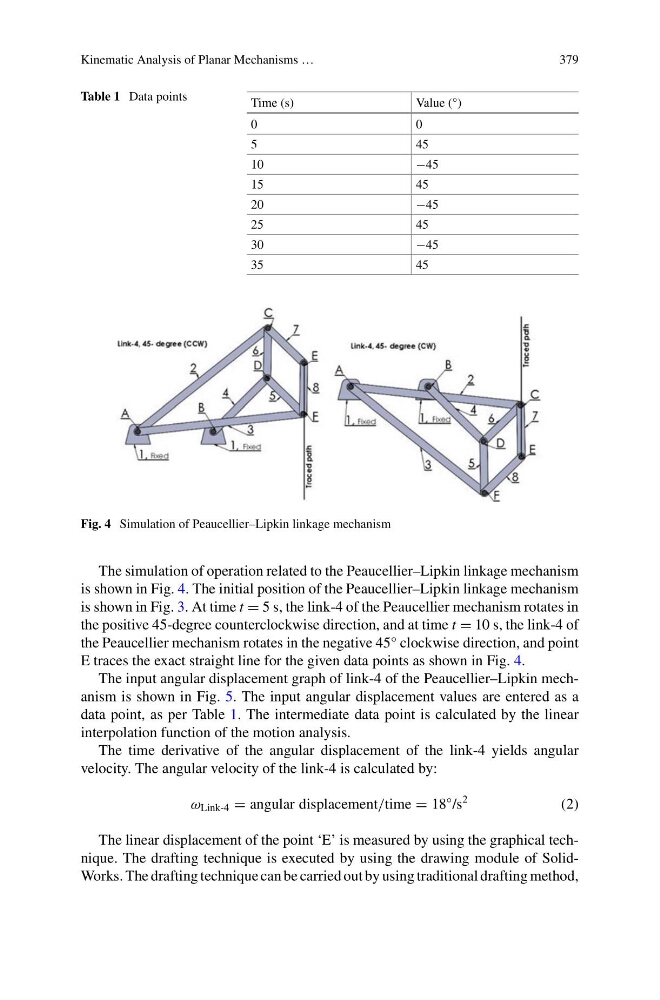
Fig. 4 Simulation of Peaucellier–Lipkin linkage mechanism
The simulation of operation related to the Peaucellier–Lipkin linkage mechanism
is shown in Fig. 4. The initial position of the Peaucellier–Lipkin linkage mechanism
is shown in Fig. 3. At time t = 5 s, the link-4 of the Peaucellier mechanism rotates in
the positive 45-degree counterclockwise direction, and at time t = 10 s, the link-4 of
the Peaucellier mechanism rotates in the negative 45° clockwise direction, and point
E traces the exact straight line for the given data points as shown in Fig. 4.
The input angular displacement graph of link-4 of the Peaucellier–Lipkin mechanism is shown in Fig. 5. The input angular displacement values are entered as a
data point, as per Table 1. The intermediate data point is calculated by the linear
interpolation function of the motion analysis.
The time derivative of the angular displacement of the link-4 yields angular
velocity. The angular velocity of the link-4 is calculated by:
ω Link-4 = angular displacement/time = 18
◦ /s
2
(2)
The linear displacement of the point ‘E’ is measured by using the graphical technique. The drafting technique is executed by using the drawing module of SolidWorks. The drafting technique can be carried out by using traditional drafting method,
379
Table 1 Data points
Time (s)
Value (°)
0
0
5
45
10
−45
15
45
20
−45
25
45
30
−45
35
45
Fig. 4 Simulation of Peaucellier–Lipkin linkage mechanism
The simulation of operation related to the Peaucellier–Lipkin linkage mechanism
is shown in Fig. 4. The initial position of the Peaucellier–Lipkin linkage mechanism
is shown in Fig. 3. At time t = 5 s, the link-4 of the Peaucellier mechanism rotates in
the positive 45-degree counterclockwise direction, and at time t = 10 s, the link-4 of
the Peaucellier mechanism rotates in the negative 45° clockwise direction, and point
E traces the exact straight line for the given data points as shown in Fig. 4.
The input angular displacement graph of link-4 of the Peaucellier–Lipkin mechanism is shown in Fig. 5. The input angular displacement values are entered as a
data point, as per Table 1. The intermediate data point is calculated by the linear
interpolation function of the motion analysis.
The time derivative of the angular displacement of the link-4 yields angular
velocity. The angular velocity of the link-4 is calculated by:
ω Link-4 = angular displacement/time = 18
◦ /s
2
(2)
The linear displacement of the point ‘E’ is measured by using the graphical technique. The drafting technique is executed by using the drawing module of SolidWorks. The drafting technique can be carried out by using traditional drafting method,