

A Study of Linear Fresnel Solar Collector Reflector …
367
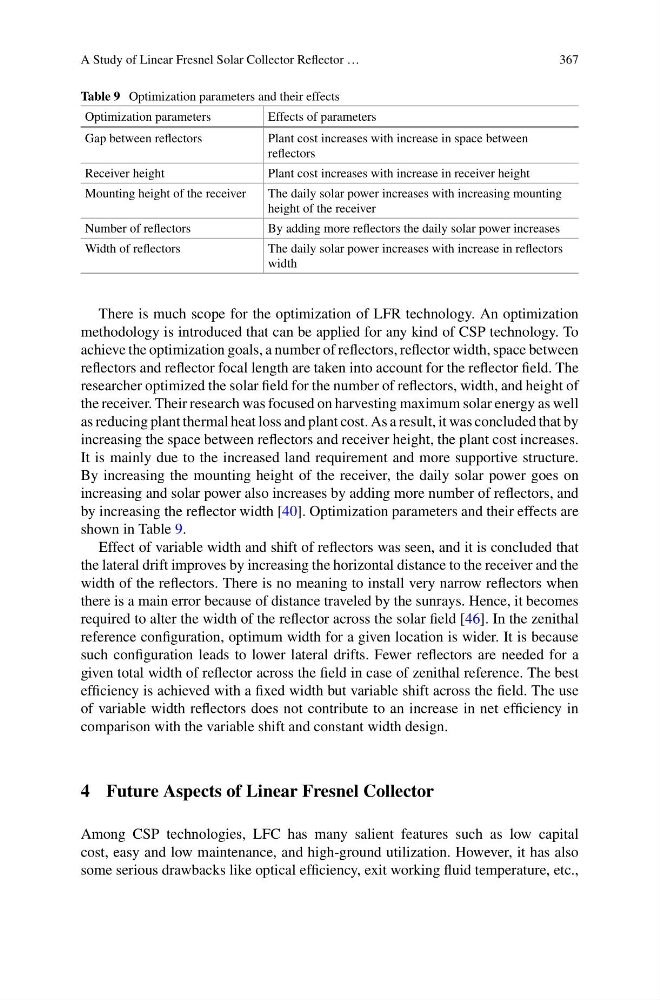
Table 9 Optimization parameters and their effects
Optimization parameters
Effects of parameters
Gap between reflectors
Plant cost increases with increase in space between
reflectors
Receiver height
Plant cost increases with increase in receiver height
Mounting height of the receiver
The daily solar power increases with increasing mounting
height of the receiver
Number of reflectors
By adding more reflectors the daily solar power increases
Width of reflectors
The daily solar power increases with increase in reflectors
width
There is much scope for the optimization of LFR technology. An optimization
methodology is introduced that can be applied for any kind of CSP technology. To
achieve the optimization goals, a number of reflectors, reflector width, space between
reflectors and reflector focal length are taken into account for the reflector field. The
researcher optimized the solar field for the number of reflectors, width, and height of
the receiver. Their research was focused on harvesting maximum solar energy as well
as reducing plant thermal heat loss and plant cost. As a result, it was concluded that by
increasing the space between reflectors and receiver height, the plant cost increases.
It is mainly due to the increased land requirement and more supportive structure.
By increasing the mounting height of the receiver, the daily solar power goes on
increasing and solar power also increases by adding more number of reflectors, and
by increasing the reflector width [40]. Optimization parameters and their effects are
shown in Table 9.
Effect of variable width and shift of reflectors was seen, and it is concluded that
the lateral drift improves by increasing the horizontal distance to the receiver and the
width of the reflectors. There is no meaning to install very narrow reflectors when
there is a main error because of distance traveled by the sunrays. Hence, it becomes
required to alter the width of the reflector across the solar field [46]. In the zenithal
reference configuration, optimum width for a given location is wider. It is because
such configuration leads to lower lateral drifts. Fewer reflectors are needed for a
given total width of reflector across the field in case of zenithal reference. The best
efficiency is achieved with a fixed width but variable shift across the field. The use
of variable width reflectors does not contribute to an increase in net efficiency in
comparison with the variable shift and constant width design.
4 Future Aspects of Linear Fresnel Collector
Among CSP technologies, LFC has many salient features such as low capital
cost, easy and low maintenance, and high-ground utilization. However, it has also
some serious drawbacks like optical efficiency, exit working fluid temperature, etc.,
367
Table 9 Optimization parameters and their effects
Optimization parameters
Effects of parameters
Gap between reflectors
Plant cost increases with increase in space between
reflectors
Receiver height
Plant cost increases with increase in receiver height
Mounting height of the receiver
The daily solar power increases with increasing mounting
height of the receiver
Number of reflectors
By adding more reflectors the daily solar power increases
Width of reflectors
The daily solar power increases with increase in reflectors
width
There is much scope for the optimization of LFR technology. An optimization
methodology is introduced that can be applied for any kind of CSP technology. To
achieve the optimization goals, a number of reflectors, reflector width, space between
reflectors and reflector focal length are taken into account for the reflector field. The
researcher optimized the solar field for the number of reflectors, width, and height of
the receiver. Their research was focused on harvesting maximum solar energy as well
as reducing plant thermal heat loss and plant cost. As a result, it was concluded that by
increasing the space between reflectors and receiver height, the plant cost increases.
It is mainly due to the increased land requirement and more supportive structure.
By increasing the mounting height of the receiver, the daily solar power goes on
increasing and solar power also increases by adding more number of reflectors, and
by increasing the reflector width [40]. Optimization parameters and their effects are
shown in Table 9.
Effect of variable width and shift of reflectors was seen, and it is concluded that
the lateral drift improves by increasing the horizontal distance to the receiver and the
width of the reflectors. There is no meaning to install very narrow reflectors when
there is a main error because of distance traveled by the sunrays. Hence, it becomes
required to alter the width of the reflector across the solar field [46]. In the zenithal
reference configuration, optimum width for a given location is wider. It is because
such configuration leads to lower lateral drifts. Fewer reflectors are needed for a
given total width of reflector across the field in case of zenithal reference. The best
efficiency is achieved with a fixed width but variable shift across the field. The use
of variable width reflectors does not contribute to an increase in net efficiency in
comparison with the variable shift and constant width design.
4 Future Aspects of Linear Fresnel Collector
Among CSP technologies, LFC has many salient features such as low capital
cost, easy and low maintenance, and high-ground utilization. However, it has also
some serious drawbacks like optical efficiency, exit working fluid temperature, etc.,