

278
R. V. Unni and M. Sreedhar Babu
3.1 The Heat Sink and the Heating Coil
The specimen was made up of two halves, having a geometric similarity with a heating
coil at the center as shown in Fig. 1. This arrangement helps in equal distribution
of heat to both the halves of HS. The base of HS was thermally insulated as largely
followed in the literature [7]. Figure 1 represents the assembly of HS and the heating
coil. Schematic view of one half of the HS depicting the notation followed in the
present work for various dimensions is as shown in Fig. 2 where, L—length of the
HS, W —base width of HS, S—spacing between the adjacent fins, H—height of
the fin, t f —thickness of fin, t b —thickness of the HS base. Heater is rectangular in
shape (180 mm × 66 mm), made through winding nichrome wire on mica sheet.
The electrical resistance of a heating coil is about 50–60 . The heating coil was
sandwiched between the two halves of HS and firmly fixed using screws and nuts at
all corners.
Fig. 1 Symmetric heat sink assembly
Fig. 2 Various notations of a heat sink
R. V. Unni and M. Sreedhar Babu
3.1 The Heat Sink and the Heating Coil
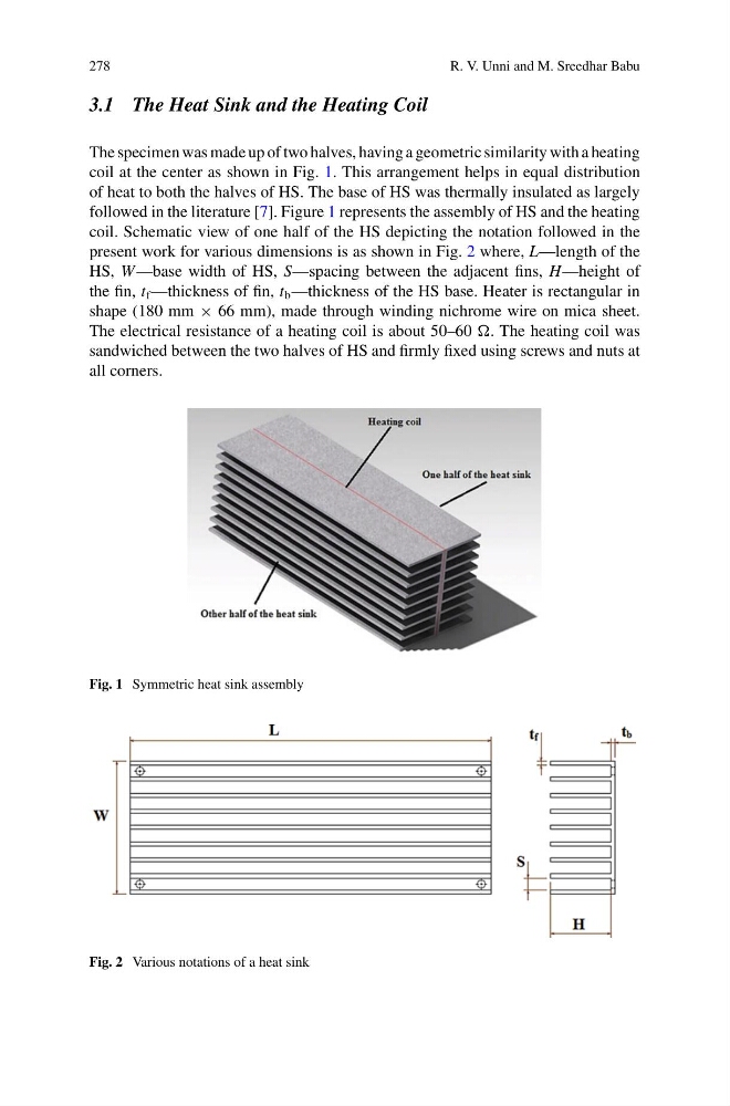
The specimen was made up of two halves, having a geometric similarity with a heating
coil at the center as shown in Fig. 1. This arrangement helps in equal distribution
of heat to both the halves of HS. The base of HS was thermally insulated as largely
followed in the literature [7]. Figure 1 represents the assembly of HS and the heating
coil. Schematic view of one half of the HS depicting the notation followed in the
present work for various dimensions is as shown in Fig. 2 where, L—length of the
HS, W —base width of HS, S—spacing between the adjacent fins, H—height of
the fin, t f —thickness of fin, t b —thickness of the HS base. Heater is rectangular in
shape (180 mm × 66 mm), made through winding nichrome wire on mica sheet.
The electrical resistance of a heating coil is about 50–60 . The heating coil was
sandwiched between the two halves of HS and firmly fixed using screws and nuts at
all corners.
Fig. 1 Symmetric heat sink assembly
Fig. 2 Various notations of a heat sink