

Experimental Investigation of Heat Sinks with and Without …
279
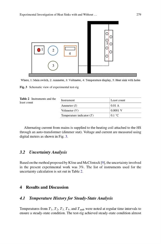
Fig. 3 Schematic view of experimental test-rig
Table 2 Instruments and the
least count
Instrument
Least count
Ammeter (I)
0.01 A
Voltmeter (V )
0.0001 V
Temperature indicator (T )
0.1 °C
Alternating current from mains is supplied to the heating coil attached to the HS
through an auto-transformer (dimmer stat). Voltage and current are measured using
digital meters as shown in Fig. 3.
3.2 Uncertainty Analysis
Based on the method proposed by Kline and McClintock [9], the uncertainty involved
in the present experimental work was 3%. The list of instruments used for the
uncertainty calculation is set out in Table 2.
4 Results and Discussion
4.1 Temperature History for Steady-State Analysis
Temperatures from T 1 , T 2 , T 3, T 4 , and T amb were noted at regular time intervals to
ensure a steady-state condition. The test-rig achieved steady-state condition almost
279
Fig. 3 Schematic view of experimental test-rig
Table 2 Instruments and the
least count
Instrument
Least count
Ammeter (I)
0.01 A
Voltmeter (V )
0.0001 V
Temperature indicator (T )
0.1 °C
Alternating current from mains is supplied to the heating coil attached to the HS
through an auto-transformer (dimmer stat). Voltage and current are measured using
digital meters as shown in Fig. 3.
3.2 Uncertainty Analysis
Based on the method proposed by Kline and McClintock [9], the uncertainty involved
in the present experimental work was 3%. The list of instruments used for the
uncertainty calculation is set out in Table 2.
4 Results and Discussion
4.1 Temperature History for Steady-State Analysis
Temperatures from T 1 , T 2 , T 3, T 4 , and T amb were noted at regular time intervals to
ensure a steady-state condition. The test-rig achieved steady-state condition almost