

226
H. H. Jadav et al.
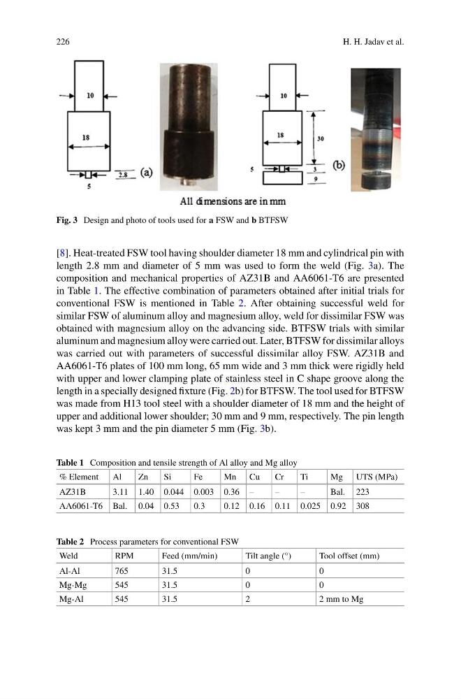
Fig. 3 Design and photo of tools used for a FSW and b BTFSW
[8]. Heat-treated FSW tool having shoulder diameter 18 mm and cylindrical pin with
length 2.8 mm and diameter of 5 mm was used to form the weld (Fig. 3a). The
composition and mechanical properties of AZ31B and AA6061-T6 are presented
in Table 1. The effective combination of parameters obtained after initial trials for
conventional FSW is mentioned in Table 2. After obtaining successful weld for
similar FSW of aluminum alloy and magnesium alloy, weld for dissimilar FSW was
obtained with magnesium alloy on the advancing side. BTFSW trials with similar
aluminum and magnesium alloy were carried out. Later, BTFSW for dissimilar alloys
was carried out with parameters of successful dissimilar alloy FSW. AZ31B and
AA6061-T6 plates of 100 mm long, 65 mm wide and 3 mm thick were rigidly held
with upper and lower clamping plate of stainless steel in C shape groove along the
length in a specially designed fixture (Fig. 2b) for BTFSW. The tool used for BTFSW
was made from H13 tool steel with a shoulder diameter of 18 mm and the height of
upper and additional lower shoulder; 30 mm and 9 mm, respectively. The pin length
was kept 3 mm and the pin diameter 5 mm (Fig. 3b).
Table 1 Composition and tensile strength of Al alloy and Mg alloy
% Element
Al
Zn
Si
Fe
Mn Cu
Cr
Ti
Mg UTS (MPa)
AZ31B
3.11 1.40 0.044 0.003 0.36 –
–
–
Bal. 223
AA6061-T6 Bal. 0.04 0.53
0.3
0.12 0.16 0.11 0.025 0.92 308
Table 2 Process parameters for conventional FSW
Weld
RPM
Feed (mm/min)
Tilt angle (°)
Tool offset (mm)
Al-Al
765
31.5
0
0
Mg-Mg
545
31.5
0
0
Mg-Al
545
31.5
2
2 mm to Mg
H. H. Jadav et al.
Fig. 3 Design and photo of tools used for a FSW and b BTFSW
[8]. Heat-treated FSW tool having shoulder diameter 18 mm and cylindrical pin with
length 2.8 mm and diameter of 5 mm was used to form the weld (Fig. 3a). The
composition and mechanical properties of AZ31B and AA6061-T6 are presented
in Table 1. The effective combination of parameters obtained after initial trials for
conventional FSW is mentioned in Table 2. After obtaining successful weld for
similar FSW of aluminum alloy and magnesium alloy, weld for dissimilar FSW was
obtained with magnesium alloy on the advancing side. BTFSW trials with similar
aluminum and magnesium alloy were carried out. Later, BTFSW for dissimilar alloys
was carried out with parameters of successful dissimilar alloy FSW. AZ31B and
AA6061-T6 plates of 100 mm long, 65 mm wide and 3 mm thick were rigidly held
with upper and lower clamping plate of stainless steel in C shape groove along the
length in a specially designed fixture (Fig. 2b) for BTFSW. The tool used for BTFSW
was made from H13 tool steel with a shoulder diameter of 18 mm and the height of
upper and additional lower shoulder; 30 mm and 9 mm, respectively. The pin length
was kept 3 mm and the pin diameter 5 mm (Fig. 3b).
Table 1 Composition and tensile strength of Al alloy and Mg alloy
% Element
Al
Zn
Si
Fe
Mn Cu
Cr
Ti
Mg UTS (MPa)
AZ31B
3.11 1.40 0.044 0.003 0.36 –
–
–
Bal. 223
AA6061-T6 Bal. 0.04 0.53
0.3
0.12 0.16 0.11 0.025 0.92 308
Table 2 Process parameters for conventional FSW
Weld
RPM
Feed (mm/min)
Tilt angle (°)
Tool offset (mm)
Al-Al
765
31.5
0
0
Mg-Mg
545
31.5
0
0
Mg-Al
545
31.5
2
2 mm to Mg