

Applicability of Bobbin Tool Friction Stir Welding …
225
with a pin or probe as compared to only top shoulder in FSW (Fig. 1b). Additional shoulder produces frictional heat at the bottom surface, avoiding temperature
gradient in thickness; forming hourglass shape (more or less rectangular) processed
zone. Conventional FSW has tapered bowl shape (triangular) processed zone. With
conventional FSW tool is inserted to the material to be welded from the top; while
in BTFSW tool is entered from the side of the material or by inserting the tool to
predrilled hole or slot and mounting lower shoulder. The tool retraction form exit or
keyhole in conventional FSW. The tool retraction step in BTFSW has three possibilities. It is completed by either allowing tool to run out forming exit hole or reversing
tool to the entry for exit or stopping tool at the end position, and upper shoulder
is retracted after dissembling bottom shoulder [7]. BTFSW was successfully used
to weld different similar aluminum alloys AA2050, AA2198-T851, AA6005-T6 by
Avettand et al. [35], Wang et al. [37], Esmaily et al. [9] respectively, magnesium alloy
AZ61 by Gaohui Li et al. [33], AZ31 by Li et al. [38] and dissimilar aluminum alloys
2024-T351 and 7075-T651 by Goetze et al. [39]. The present work aims to explore
applicability of BTFSW for dissimilar Al-Mg joint which is probably the first attempt
to the best of authors’ knowledge. Initially, dissimilar welding of aluminum alloy
and magnesium alloy was successfully carried out with conventional FSW. Further,
similar parameters were used for dissimilar BTFSW experiments.
2 Experimental Procedure
In the present experiment, for conventional FSW, 100-mm-long, 50-mm-wide and 3mm-thick sheets of AZ31B and AA6061-T6 were used. The sheets were cut, cleaned
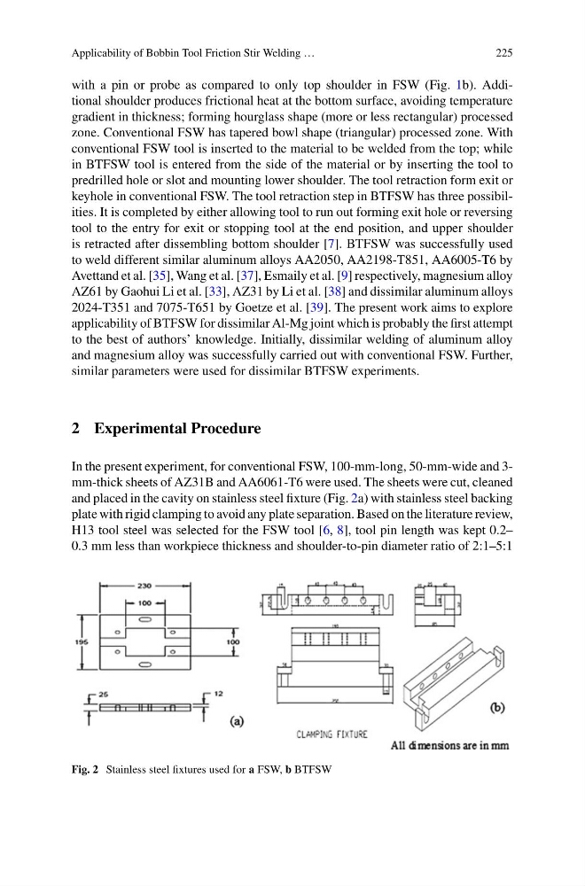
and placed in the cavity on stainless steel fixture (Fig. 2a) with stainless steel backing
plate with rigid clamping to avoid any plate separation. Based on the literature review,
H13 tool steel was selected for the FSW tool [6, 8], tool pin length was kept 0.2–
0.3 mm less than workpiece thickness and shoulder-to-pin diameter ratio of 2:1–5:1
Fig. 2 Stainless steel fixtures used for a FSW, b BTFSW
225
with a pin or probe as compared to only top shoulder in FSW (Fig. 1b). Additional shoulder produces frictional heat at the bottom surface, avoiding temperature
gradient in thickness; forming hourglass shape (more or less rectangular) processed
zone. Conventional FSW has tapered bowl shape (triangular) processed zone. With
conventional FSW tool is inserted to the material to be welded from the top; while
in BTFSW tool is entered from the side of the material or by inserting the tool to
predrilled hole or slot and mounting lower shoulder. The tool retraction form exit or
keyhole in conventional FSW. The tool retraction step in BTFSW has three possibilities. It is completed by either allowing tool to run out forming exit hole or reversing
tool to the entry for exit or stopping tool at the end position, and upper shoulder
is retracted after dissembling bottom shoulder [7]. BTFSW was successfully used
to weld different similar aluminum alloys AA2050, AA2198-T851, AA6005-T6 by
Avettand et al. [35], Wang et al. [37], Esmaily et al. [9] respectively, magnesium alloy
AZ61 by Gaohui Li et al. [33], AZ31 by Li et al. [38] and dissimilar aluminum alloys
2024-T351 and 7075-T651 by Goetze et al. [39]. The present work aims to explore
applicability of BTFSW for dissimilar Al-Mg joint which is probably the first attempt
to the best of authors’ knowledge. Initially, dissimilar welding of aluminum alloy
and magnesium alloy was successfully carried out with conventional FSW. Further,
similar parameters were used for dissimilar BTFSW experiments.
2 Experimental Procedure
In the present experiment, for conventional FSW, 100-mm-long, 50-mm-wide and 3mm-thick sheets of AZ31B and AA6061-T6 were used. The sheets were cut, cleaned
and placed in the cavity on stainless steel fixture (Fig. 2a) with stainless steel backing
plate with rigid clamping to avoid any plate separation. Based on the literature review,
H13 tool steel was selected for the FSW tool [6, 8], tool pin length was kept 0.2–
0.3 mm less than workpiece thickness and shoulder-to-pin diameter ratio of 2:1–5:1
Fig. 2 Stainless steel fixtures used for a FSW, b BTFSW