

The new design concept that you are asked to examine concerns replacing the
cantilever microbeam with a simply supported beam, whose dynamical properties
to some extent can be adjusted by means of externally applied axial thrust and
damping. In this preliminary study, the dynamics of the microbeam in itself, i.e. in
the absence of interatomic forces, is of primary interest. This will form the basis for
understanding and predicting dynamical responses in the presence of a sample to be
scanned, i.e. when the atoms of the AFM tip are interacting with atoms on a sample
surface.
B.3.1 System Description
The beam in Fig. B.4(a) is simply supported at the ends, is made of linearly elastic
material, and has length L, flexural stiffness EI, and mass per unit length qA.
Transverse deformations are described by U(X, t), whereas stretching of the beam
axis, shear deformations, longitudinal inertia, and rotary inertia can be neglected.
Rotations of beam segments are sufficiently small that j = U′′(X, t) is a good
approximation, with j being curvature and ()′ ∂/∂X. Dissipation of beam energy
can be modeled as internal viscous damping, i.e. the internal bending moment is
EIj + C 1 EI _
j, where (
: ) ∂/∂t and C 1 is the coefficient of internal damping.
One beam support is movable, and is connected to a point B through a linear
spring having stiffness K. Fig. B.4(a) shows the beam and the spring undeformed,
whereas Fig. B.4(b) shows a deformed state. The position q(t)L of point B with
respect to a fixed boundary is externally controlled by piezoelectric ceramics, so
that q(t) = q 0 + q 1 cos(Xt), where q 0 , q 1 , and X are the control parameters (q 0 can be
assigned positive as well as negative values). The compression of the spring is q(t)
L − Z(t), where q(t) is known (controlled), whereas Z(t) is the shortening in the
distance between beam supports that occurs when the beam deforms, U(X, t) 6 ¼ 0. In
Fig. B.4(b) Z is shown greatly exaggerated. In addition, to supply more control
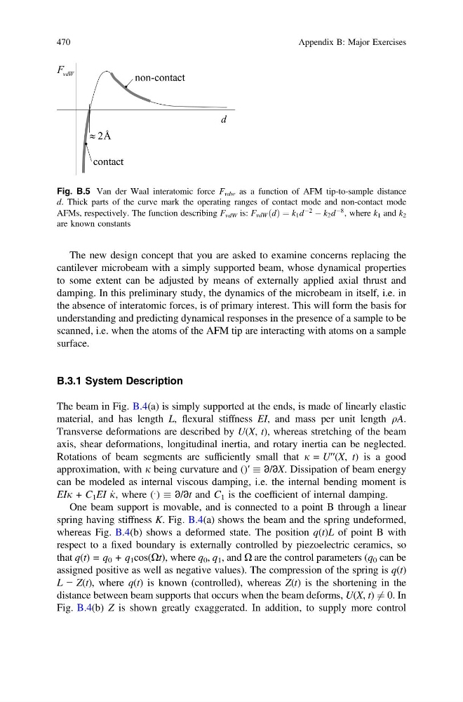
Fig. B.5 Van der Waal interatomic force F vdw as a function of AFM tip-to-sample distance
d. Thick parts of the curve mark the operating ranges of contact mode and non-contact mode
AFMs, respectively. The function describing F vdW is: F vdW ðdÞ ¼ k 1 d
À2 À k 2 d
À8 , where k 1 and k 2
are known constants
470
Appendix B: Major Exercises
cantilever microbeam with a simply supported beam, whose dynamical properties
to some extent can be adjusted by means of externally applied axial thrust and
damping. In this preliminary study, the dynamics of the microbeam in itself, i.e. in
the absence of interatomic forces, is of primary interest. This will form the basis for
understanding and predicting dynamical responses in the presence of a sample to be
scanned, i.e. when the atoms of the AFM tip are interacting with atoms on a sample
surface.
B.3.1 System Description
The beam in Fig. B.4(a) is simply supported at the ends, is made of linearly elastic
material, and has length L, flexural stiffness EI, and mass per unit length qA.
Transverse deformations are described by U(X, t), whereas stretching of the beam
axis, shear deformations, longitudinal inertia, and rotary inertia can be neglected.
Rotations of beam segments are sufficiently small that j = U′′(X, t) is a good
approximation, with j being curvature and ()′ ∂/∂X. Dissipation of beam energy
can be modeled as internal viscous damping, i.e. the internal bending moment is
EIj + C 1 EI _
j, where (
: ) ∂/∂t and C 1 is the coefficient of internal damping.
One beam support is movable, and is connected to a point B through a linear
spring having stiffness K. Fig. B.4(a) shows the beam and the spring undeformed,
whereas Fig. B.4(b) shows a deformed state. The position q(t)L of point B with
respect to a fixed boundary is externally controlled by piezoelectric ceramics, so
that q(t) = q 0 + q 1 cos(Xt), where q 0 , q 1 , and X are the control parameters (q 0 can be
assigned positive as well as negative values). The compression of the spring is q(t)
L − Z(t), where q(t) is known (controlled), whereas Z(t) is the shortening in the
distance between beam supports that occurs when the beam deforms, U(X, t) 6 ¼ 0. In
Fig. B.4(b) Z is shown greatly exaggerated. In addition, to supply more control
Fig. B.5 Van der Waal interatomic force F vdw as a function of AFM tip-to-sample distance
d. Thick parts of the curve mark the operating ranges of contact mode and non-contact mode
AFMs, respectively. The function describing F vdW is: F vdW ðdÞ ¼ k 1 d
À2 À k 2 d
À8 , where k 1 and k 2
are known constants
470
Appendix B: Major Exercises