

B.2 Vibrations of a Spring-Tensioned Beam
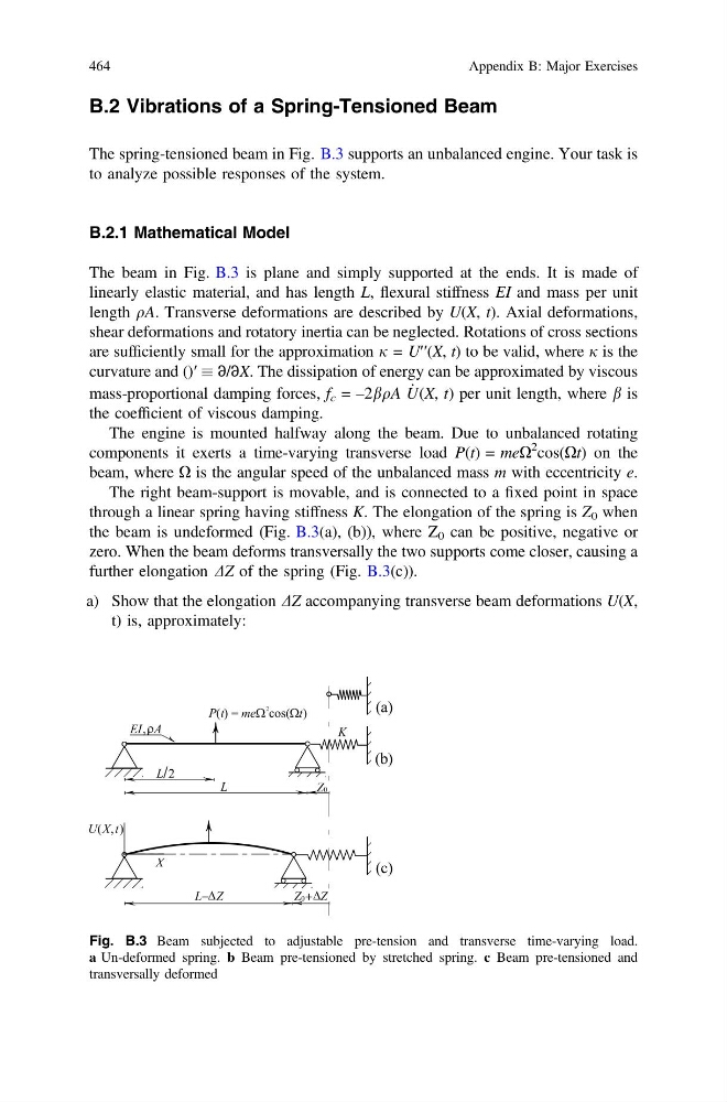
The spring-tensioned beam in Fig. B.3 supports an unbalanced engine. Your task is
to analyze possible responses of the system.
B.2.1 Mathematical Model
The beam in Fig. B.3 is plane and simply supported at the ends. It is made of
linearly elastic material, and has length L, flexural stiffness EI and mass per unit
length qA. Transverse deformations are described by U(X, t). Axial deformations,
shear deformations and rotatory inertia can be neglected. Rotations of cross sections
are sufficiently small for the approximation j = U′′(X, t) to be valid, where j is the
curvature and ()′ ∂/∂X. The dissipation of energy can be approximated by viscous
mass-proportional damping forces, f c = –2bqA _
U(X, t) per unit length, where b is
the coefficient of viscous damping.
The engine is mounted halfway along the beam. Due to unbalanced rotating
components it exerts a time-varying transverse load P(t) = meX
2 cos(Xt) on the
beam, where X is the angular speed of the unbalanced mass m with eccentricity e.
The right beam-support is movable, and is connected to a fixed point in space
through a linear spring having stiffness K. The elongation of the spring is Z 0 when
the beam is undeformed (Fig. B.3(a), (b)), where Z 0 can be positive, negative or
zero. When the beam deforms transversally the two supports come closer, causing a
further elongation DZ of the spring (Fig. B.3(c)).
a) Show that the elongation DZ accompanying transverse beam deformations U(X,
t) is, approximately:
Fig. B.3 Beam subjected to adjustable pre-tension and transverse time-varying load.
a Un-deformed spring. b Beam pre-tensioned by stretched spring. c Beam pre-tensioned and
transversally deformed
464
Appendix B: Major Exercises
The spring-tensioned beam in Fig. B.3 supports an unbalanced engine. Your task is
to analyze possible responses of the system.
B.2.1 Mathematical Model
The beam in Fig. B.3 is plane and simply supported at the ends. It is made of
linearly elastic material, and has length L, flexural stiffness EI and mass per unit
length qA. Transverse deformations are described by U(X, t). Axial deformations,
shear deformations and rotatory inertia can be neglected. Rotations of cross sections
are sufficiently small for the approximation j = U′′(X, t) to be valid, where j is the
curvature and ()′ ∂/∂X. The dissipation of energy can be approximated by viscous
mass-proportional damping forces, f c = –2bqA _
U(X, t) per unit length, where b is
the coefficient of viscous damping.
The engine is mounted halfway along the beam. Due to unbalanced rotating
components it exerts a time-varying transverse load P(t) = meX
2 cos(Xt) on the
beam, where X is the angular speed of the unbalanced mass m with eccentricity e.
The right beam-support is movable, and is connected to a fixed point in space
through a linear spring having stiffness K. The elongation of the spring is Z 0 when
the beam is undeformed (Fig. B.3(a), (b)), where Z 0 can be positive, negative or
zero. When the beam deforms transversally the two supports come closer, causing a
further elongation DZ of the spring (Fig. B.3(c)).
a) Show that the elongation DZ accompanying transverse beam deformations U(X,
t) is, approximately:
Fig. B.3 Beam subjected to adjustable pre-tension and transverse time-varying load.
a Un-deformed spring. b Beam pre-tensioned by stretched spring. c Beam pre-tensioned and
transversally deformed
464
Appendix B: Major Exercises