

stiffening effect of HF excitation is responsible for stabilizing the pendulum near the
up-pointing position.
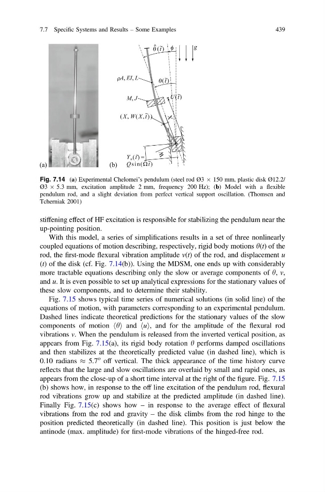
With this model, a series of simplifications results in a set of three nonlinearly
coupled equations of motion describing, respectively, rigid body motions h(t) of the
rod, the first-mode flexural vibration amplitude v(t) of the rod, and displacement u
(t) of the disk (cf. Fig. 7.14(b)). Using the MDSM, one ends up with considerably
more tractable equations describing only the slow or average components of h, v,
and u. It is even possible to set up analytical expressions for the stationary values of
these slow components, and to determine their stability.
Fig. 7.15 shows typical time series of numerical solutions (in solid line) of the
equations of motion, with parameters corresponding to an experimental pendulum.
Dashed lines indicate theoretical predictions for the stationary values of the slow
components of motion h
h i and u
h i, and for the amplitude of the flexural rod
vibrations v. When the pendulum is released from the inverted vertical position, as
appears from Fig. 7.15(a), its rigid body rotation h performs damped oscillations
and then stabilizes at the theoretically predicted value (in dashed line), which is
0.10 radians % 5.7
o off vertical. The thick appearance of the time history curve
reflects that the large and slow oscillations are overlaid by small and rapid ones, as
appears from the close-up of a short time interval at the right of the figure. Fig. 7.15
(b) shows how, in response to the off line excitation of the pendulum rod, flexural
rod vibrations grow up and stabilize at the predicted amplitude (in dashed line).
Finally Fig. 7.15(c) shows how – in response to the average effect of flexural
vibrations from the rod and gravity – the disk climbs from the rod hinge to the
position predicted theoretically (in dashed line). This position is just below the
antinode (max. amplitude) for first-mode vibrations of the hinged-free rod.
Fig. 7.14 (a) Experimental Chelomei’s pendulum (steel rod Ø3 Â 150 mm, plastic disk Ø12.2/
Ø3 Â 5.3 mm, excitation amplitude 2 mm, frequency 200 Hz); (b) Model with a flexible
pendulum rod, and a slight deviation from perfect vertical support oscillation. (Thomsen and
Tcherniak 2001)
7.7 Specific Systems and Results – Some Examples
439
up-pointing position.
With this model, a series of simplifications results in a set of three nonlinearly
coupled equations of motion describing, respectively, rigid body motions h(t) of the
rod, the first-mode flexural vibration amplitude v(t) of the rod, and displacement u
(t) of the disk (cf. Fig. 7.14(b)). Using the MDSM, one ends up with considerably
more tractable equations describing only the slow or average components of h, v,
and u. It is even possible to set up analytical expressions for the stationary values of
these slow components, and to determine their stability.
Fig. 7.15 shows typical time series of numerical solutions (in solid line) of the
equations of motion, with parameters corresponding to an experimental pendulum.
Dashed lines indicate theoretical predictions for the stationary values of the slow
components of motion h
h i and u
h i, and for the amplitude of the flexural rod
vibrations v. When the pendulum is released from the inverted vertical position, as
appears from Fig. 7.15(a), its rigid body rotation h performs damped oscillations
and then stabilizes at the theoretically predicted value (in dashed line), which is
0.10 radians % 5.7
o off vertical. The thick appearance of the time history curve
reflects that the large and slow oscillations are overlaid by small and rapid ones, as
appears from the close-up of a short time interval at the right of the figure. Fig. 7.15
(b) shows how, in response to the off line excitation of the pendulum rod, flexural
rod vibrations grow up and stabilize at the predicted amplitude (in dashed line).
Finally Fig. 7.15(c) shows how – in response to the average effect of flexural
vibrations from the rod and gravity – the disk climbs from the rod hinge to the
position predicted theoretically (in dashed line). This position is just below the
antinode (max. amplitude) for first-mode vibrations of the hinged-free rod.
Fig. 7.14 (a) Experimental Chelomei’s pendulum (steel rod Ø3 Â 150 mm, plastic disk Ø12.2/
Ø3 Â 5.3 mm, excitation amplitude 2 mm, frequency 200 Hz); (b) Model with a flexible
pendulum rod, and a slight deviation from perfect vertical support oscillation. (Thomsen and
Tcherniak 2001)
7.7 Specific Systems and Results – Some Examples
439