

averaging for obtaining stationary responses of a 2-DOF system, and how to obtain
transient responses to sweep excitation.
4.8 Vibration-Induced Fluid Flow in Pipes
Nonlinear vibrations may induce large-scale motion of solid bodies, as illustrated
in Sects. 4.6–4.7. Can fluid particles be brought into organized movement as well?
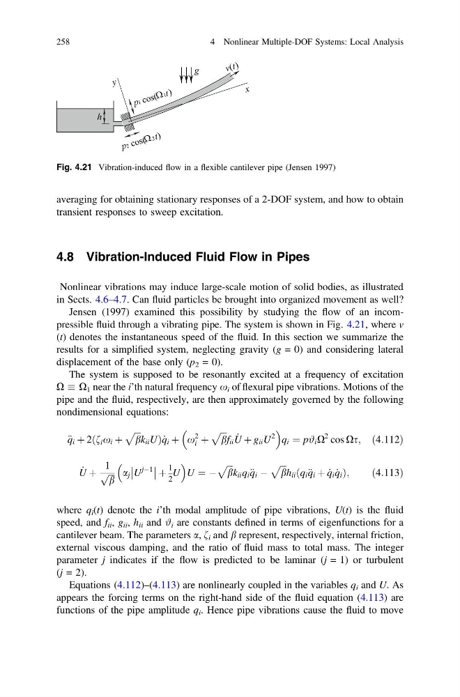
Jensen (1997) examined this possibility by studying the flow of an incompressible fluid through a vibrating pipe. The system is shown in Fig. 4.21, where v
(t) denotes the instantaneous speed of the fluid. In this section we summarize the
results for a simplified system, neglecting gravity (g = 0) and considering lateral
displacement of the base only (p 2 = 0).
The system is supposed to be resonantly excited at a frequency of excitation
X X 1 near the i’th natural frequency x i of flexural pipe vibrations. Motions of the
pipe and the fluid, respectively, are then approximately governed by the following
nondimensional equations:
€ q i þ 2ðf i x i þ
ffiffiffi
b
p
k ii UÞ _
q i þ x
2
i þ
ffiffiffi
b
p
f ii _
U þ g ii U
2
q i ¼ p# i X
2 cos Xs; ð4:112Þ
_
U þ
1
ffiffiffi
b
p a j U
jÀ1
þ
1
2
U
U ¼ À
ffiffiffi
b
p
k ii q i € q i À
ffiffiffi
b
p
h ii ðq i € q i þ _
q i _
q i Þ;
ð4:113Þ
where q i (t) denote the i’th modal amplitude of pipe vibrations, U(t) is the fluid
speed, and f ii , g ii , h ii and # i are constants defined in terms of eigenfunctions for a
cantilever beam. The parameters a, f i and b represent, respectively, internal friction,
external viscous damping, and the ratio of fluid mass to total mass. The integer
parameter j indicates if the flow is predicted to be laminar (j = 1) or turbulent
(j = 2).
Equations (4.112)–(4.113) are nonlinearly coupled in the variables q i and U. As
appears the forcing terms on the right-hand side of the fluid equation (4.113) are
functions of the pipe amplitude q i . Hence pipe vibrations cause the fluid to move
Fig. 4.21 Vibration-induced flow in a flexible cantilever pipe (Jensen 1997)
258
4 Nonlinear Multiple-DOF Systems: Local Analysis
transient responses to sweep excitation.
4.8 Vibration-Induced Fluid Flow in Pipes
Nonlinear vibrations may induce large-scale motion of solid bodies, as illustrated
in Sects. 4.6–4.7. Can fluid particles be brought into organized movement as well?
Jensen (1997) examined this possibility by studying the flow of an incompressible fluid through a vibrating pipe. The system is shown in Fig. 4.21, where v
(t) denotes the instantaneous speed of the fluid. In this section we summarize the
results for a simplified system, neglecting gravity (g = 0) and considering lateral
displacement of the base only (p 2 = 0).
The system is supposed to be resonantly excited at a frequency of excitation
X X 1 near the i’th natural frequency x i of flexural pipe vibrations. Motions of the
pipe and the fluid, respectively, are then approximately governed by the following
nondimensional equations:
€ q i þ 2ðf i x i þ
ffiffiffi
b
p
k ii UÞ _
q i þ x
2
i þ
ffiffiffi
b
p
f ii _
U þ g ii U
2
q i ¼ p# i X
2 cos Xs; ð4:112Þ
_
U þ
1
ffiffiffi
b
p a j U
jÀ1
þ
1
2
U
U ¼ À
ffiffiffi
b
p
k ii q i € q i À
ffiffiffi
b
p
h ii ðq i € q i þ _
q i _
q i Þ;
ð4:113Þ
where q i (t) denote the i’th modal amplitude of pipe vibrations, U(t) is the fluid
speed, and f ii , g ii , h ii and # i are constants defined in terms of eigenfunctions for a
cantilever beam. The parameters a, f i and b represent, respectively, internal friction,
external viscous damping, and the ratio of fluid mass to total mass. The integer
parameter j indicates if the flow is predicted to be laminar (j = 1) or turbulent
(j = 2).
Equations (4.112)–(4.113) are nonlinearly coupled in the variables q i and U. As
appears the forcing terms on the right-hand side of the fluid equation (4.113) are
functions of the pipe amplitude q i . Hence pipe vibrations cause the fluid to move
Fig. 4.21 Vibration-induced flow in a flexible cantilever pipe (Jensen 1997)
258
4 Nonlinear Multiple-DOF Systems: Local Analysis