

without causing additional complications in the procedure. This is illustrated in
Sects. 3.9.5 and 3.9.6.
3.9.4 Example 2: Mass in a Clearance
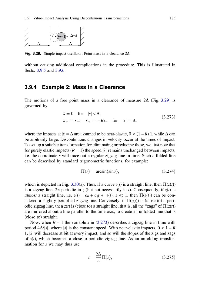
The motions of a free point mass in a clearance of measure 2D (Fig. 3.29) is
governed by:
€ s ¼ 0 for s
j j\D;
s þ ¼ s À ; _
s þ ¼ ÀR_ s À for s
j j ¼ D;
ð3:273Þ
where the impacts at |s| = D are assumed to be near-elastic, 0 < (1 – R) 1, while D can
be arbitrarily large. Discontinuous changes in velocity occur at the times of impact.
To set up a suitable transformation for eliminating or reducing these, we first note that
for purely elastic impacts (R = 1) the speed _
s
j j remains unchanged between impacts,
i.e. the coordinate s will trace out a regular zigzag line in time. Such a folded line
can be described by standard trigonometric functions, for example:
P z
ð Þ ¼ arcsin sin z
ð
Þ;
ð3:274Þ
which is depicted in Fig. 3.30(a). Thus, if a curve z(t) is a straight line, then P(z(t))
is a zigzag line, 2p-periodic in z (but not necessarily in t). Consequently, if z(t) is
almost a straight line, i.e. z(t) = c 0 + c 1 t + e(t), e ( 1, then P(z(t)) can be considered a slightly perturbed zigzag line. Conversely, if P(z(t)) is (close to) a periodic zigzag line, then z(t) is (close to) a straight line, that is, all the “zags” of P(z(t))
are mirrored about a line parallel to the time axis, to create an unfolded line that is
(close to) straight.
Now, when R = 1 the variable s in (3.273) describes a zigzag line in time with
period 4D/ _
s
j j, where _
s
j j is the constant speed. With near-elastic impacts, 0 < 1 – R
1, _
s
j j will decrease at bit at every impact, and so will the slopes of the zigs and zags
of s(t), which becomes a close-to-periodic zigzag line. As an unfolding transformation for s we may thus use
s ¼
2D
p
PðzÞ;
ð3:275Þ
Fig. 3.29. Simple impact oscillator: Point mass in a clearance 2D
3.9 Vibro-Impact Analysis Using Discontinuous Transformations
185
Sects. 3.9.5 and 3.9.6.
3.9.4 Example 2: Mass in a Clearance
The motions of a free point mass in a clearance of measure 2D (Fig. 3.29) is
governed by:
€ s ¼ 0 for s
j j\D;
s þ ¼ s À ; _
s þ ¼ ÀR_ s À for s
j j ¼ D;
ð3:273Þ
where the impacts at |s| = D are assumed to be near-elastic, 0 < (1 – R) 1, while D can
be arbitrarily large. Discontinuous changes in velocity occur at the times of impact.
To set up a suitable transformation for eliminating or reducing these, we first note that
for purely elastic impacts (R = 1) the speed _
s
j j remains unchanged between impacts,
i.e. the coordinate s will trace out a regular zigzag line in time. Such a folded line
can be described by standard trigonometric functions, for example:
P z
ð Þ ¼ arcsin sin z
ð
Þ;
ð3:274Þ
which is depicted in Fig. 3.30(a). Thus, if a curve z(t) is a straight line, then P(z(t))
is a zigzag line, 2p-periodic in z (but not necessarily in t). Consequently, if z(t) is
almost a straight line, i.e. z(t) = c 0 + c 1 t + e(t), e ( 1, then P(z(t)) can be considered a slightly perturbed zigzag line. Conversely, if P(z(t)) is (close to) a periodic zigzag line, then z(t) is (close to) a straight line, that is, all the “zags” of P(z(t))
are mirrored about a line parallel to the time axis, to create an unfolded line that is
(close to) straight.
Now, when R = 1 the variable s in (3.273) describes a zigzag line in time with
period 4D/ _
s
j j, where _
s
j j is the constant speed. With near-elastic impacts, 0 < 1 – R
1, _
s
j j will decrease at bit at every impact, and so will the slopes of the zigs and zags
of s(t), which becomes a close-to-periodic zigzag line. As an unfolding transformation for s we may thus use
s ¼
2D
p
PðzÞ;
ð3:275Þ
Fig. 3.29. Simple impact oscillator: Point mass in a clearance 2D
3.9 Vibro-Impact Analysis Using Discontinuous Transformations
185