

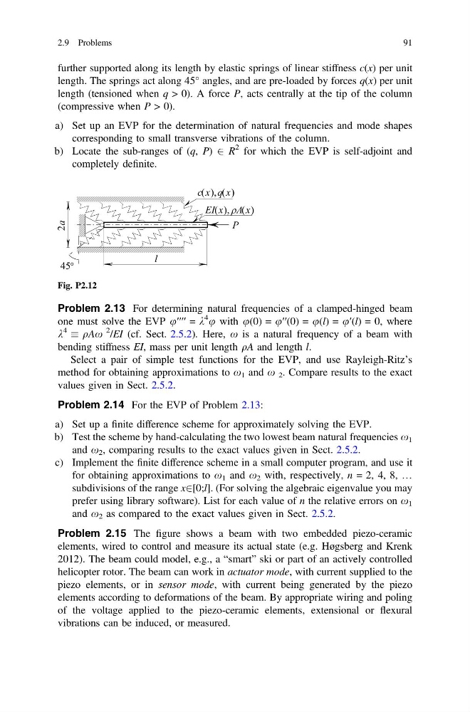
further supported along its length by elastic springs of linear stiffness c(x) per unit
length. The springs act along 45° angles, and are pre-loaded by forces q(x) per unit
length (tensioned when q > 0). A force P, acts centrally at the tip of the column
(compressive when P > 0).
a) Set up an EVP for the determination of natural frequencies and mode shapes
corresponding to small transverse vibrations of the column.
b) Locate the sub-ranges of (q, P) 2 R
2 for which the EVP is self-adjoint and
completely definite.
Problem 2.13 For determining natural frequencies of a clamped-hinged beam
one must solve the EVP u′′′′ = k
4 u with u(0) = u′′(0) = u(l) = u′(l) = 0, where
k
4
qAx
2 /EI (cf. Sect. 2.5.2). Here, x is a natural frequency of a beam with
bending stiffness EI, mass per unit length qA and length l.
Select a pair of simple test functions for the EVP, and use Rayleigh-Ritz’s
method for obtaining approximations to x 1 and x 2 . Compare results to the exact
values given in Sect. 2.5.2.
Problem 2.14 For the EVP of Problem 2.13:
a) Set up a finite difference scheme for approximately solving the EVP.
b) Test the scheme by hand-calculating the two lowest beam natural frequencies x 1
and x 2 , comparing results to the exact values given in Sect. 2.5.2.
c) Implement the finite difference scheme in a small computer program, and use it
for obtaining approximations to x 1 and x 2 with, respectively, n = 2, 4, 8, …
subdivisions of the range x2[0;l]. (For solving the algebraic eigenvalue you may
prefer using library software). List for each value of n the relative errors on x 1
and x 2 as compared to the exact values given in Sect. 2.5.2.
Problem 2.15 The figure shows a beam with two embedded piezo-ceramic
elements, wired to control and measure its actual state (e.g. Høgsberg and Krenk
2012). The beam could model, e.g., a “smart” ski or part of an actively controlled
helicopter rotor. The beam can work in actuator mode, with current supplied to the
piezo elements, or in sensor mode, with current being generated by the piezo
elements according to deformations of the beam. By appropriate wiring and poling
of the voltage applied to the piezo-ceramic elements, extensional or flexural
vibrations can be induced, or measured.
Fig. P2.12
2.9 Problems
91
length. The springs act along 45° angles, and are pre-loaded by forces q(x) per unit
length (tensioned when q > 0). A force P, acts centrally at the tip of the column
(compressive when P > 0).
a) Set up an EVP for the determination of natural frequencies and mode shapes
corresponding to small transverse vibrations of the column.
b) Locate the sub-ranges of (q, P) 2 R
2 for which the EVP is self-adjoint and
completely definite.
Problem 2.13 For determining natural frequencies of a clamped-hinged beam
one must solve the EVP u′′′′ = k
4 u with u(0) = u′′(0) = u(l) = u′(l) = 0, where
k
4
qAx
2 /EI (cf. Sect. 2.5.2). Here, x is a natural frequency of a beam with
bending stiffness EI, mass per unit length qA and length l.
Select a pair of simple test functions for the EVP, and use Rayleigh-Ritz’s
method for obtaining approximations to x 1 and x 2 . Compare results to the exact
values given in Sect. 2.5.2.
Problem 2.14 For the EVP of Problem 2.13:
a) Set up a finite difference scheme for approximately solving the EVP.
b) Test the scheme by hand-calculating the two lowest beam natural frequencies x 1
and x 2 , comparing results to the exact values given in Sect. 2.5.2.
c) Implement the finite difference scheme in a small computer program, and use it
for obtaining approximations to x 1 and x 2 with, respectively, n = 2, 4, 8, …
subdivisions of the range x2[0;l]. (For solving the algebraic eigenvalue you may
prefer using library software). List for each value of n the relative errors on x 1
and x 2 as compared to the exact values given in Sect. 2.5.2.
Problem 2.15 The figure shows a beam with two embedded piezo-ceramic
elements, wired to control and measure its actual state (e.g. Høgsberg and Krenk
2012). The beam could model, e.g., a “smart” ski or part of an actively controlled
helicopter rotor. The beam can work in actuator mode, with current supplied to the
piezo elements, or in sensor mode, with current being generated by the piezo
elements according to deformations of the beam. By appropriate wiring and poling
of the voltage applied to the piezo-ceramic elements, extensional or flexural
vibrations can be induced, or measured.
Fig. P2.12
2.9 Problems
91