

75
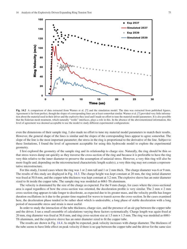
even the dimensions of their sample ring. I also made no effort to tune my material model parameters to match their results.
However, the general shape of the lines is similar and the slopes of the corresponding lines appear to agree somewhat. The
slope of the line is the most important parameter; the stress in the ring is proportional to the derivative of the line. Subject to
these limitations, I found the level of agreement acceptable for using this hydrocode model to explore the experimental
geometry.
I first explored the geometry of the sample ring and its relationship to charge size. Naturally, the ring should be thin so
that stress waves damp out quickly as they traverse the cross-section of the ring and because it is preferable to have the ring
very thin relative to the inner diameter to preserve the assumption of uniaxial stress. However, a very thin ring will also be
more fragile and, depending on the microstructural characteristic length scale(s), a very thin ring may not contain a representative microstructure.
For this study, I tested cases where the ring was 1 or 2 mm tall and 1 or 2 mm thick. The charge diameter was 6 or 9 mm.
The results of this study are displayed in Fig. 14.3. The charge height was kept constant at 20 mm, the ring initial diameter
was fixed at 50.8 mm, and the copper tube thickness was kept constant at 3.2 mm. The explosive sleeve has an outer diameter
sized to fit inside the copper tube. The sample ring was modeled as 6061-T6 aluminum.
The velocity is dominated by the size of the charge as expected. For the 9 mm charge, for cases where the cross- sectional
area is equal regardless of how the cross-section was oriented, the deceleration profile is very similar. The 2 mm × 2 mm
cross-section ring appears to take longer to decelerate, as expected due to its greater mass, and the velocity profile has longer
duration oscillations in it due to the greater time required for waves to transit across the cross- section. In the cases examined
here, the deceleration phase tended to be rather short which is undesirable; a long phase of stable deceleration with a long
period of measurable stress and strain is most useful.
In order to study the interaction of the tube thickness, charge size, and the presence of an air gap between the copper tube
and the driver, I ran a small ensemble of calculations varying these factors systematically. Charge length was again fixed at
20 mm, ring diameter was fixed at 50.8 mm, and ring cross-section size at 1.5 mm × 1.5 mm. The ring was modeled as 6061T6 aluminum, and the explosive sleeve has an outer diameter sized to fit the copper tube.
The results are shown in Fig. 14.4. As might be expected, peak velocity increases with charge diameter. The thickness of
the tube seems to have little effect on peak velocity if there is no gap between the copper tube and the driver for the same size
0
20
40
60
80
100
120
140
160
0
5
10
15
20
25
30
Ring Velocity (m/s)
Time (us)
Exp 2537
Simulated 2537
Exp 2539
Simulated 2539
Fig. 14.2 A comparison of data extracted from Warnes et al. [7] and the simulation model. The data was extracted from published figures.
Agreement is far from perfect, though the slopes of corresponding lines are at least somewhat similar. Warnes et al. [7] provided very little information about the material used in their driver and the explosive they used and I made no effort to tune the material model parameters. It is also possible
that the Eulerian mesh treatment, which naturally “welds” interfaces, plays a role in this. In the absence of the abovementioned information, this
level of agreement was deemed acceptable to use the model to study different experimental configurations
14 Analysis of the Explosively Driven Expanding Ring Tension Test
even the dimensions of their sample ring. I also made no effort to tune my material model parameters to match their results.
However, the general shape of the lines is similar and the slopes of the corresponding lines appear to agree somewhat. The
slope of the line is the most important parameter; the stress in the ring is proportional to the derivative of the line. Subject to
these limitations, I found the level of agreement acceptable for using this hydrocode model to explore the experimental
geometry.
I first explored the geometry of the sample ring and its relationship to charge size. Naturally, the ring should be thin so
that stress waves damp out quickly as they traverse the cross-section of the ring and because it is preferable to have the ring
very thin relative to the inner diameter to preserve the assumption of uniaxial stress. However, a very thin ring will also be
more fragile and, depending on the microstructural characteristic length scale(s), a very thin ring may not contain a representative microstructure.
For this study, I tested cases where the ring was 1 or 2 mm tall and 1 or 2 mm thick. The charge diameter was 6 or 9 mm.
The results of this study are displayed in Fig. 14.3. The charge height was kept constant at 20 mm, the ring initial diameter
was fixed at 50.8 mm, and the copper tube thickness was kept constant at 3.2 mm. The explosive sleeve has an outer diameter
sized to fit inside the copper tube. The sample ring was modeled as 6061-T6 aluminum.
The velocity is dominated by the size of the charge as expected. For the 9 mm charge, for cases where the cross- sectional
area is equal regardless of how the cross-section was oriented, the deceleration profile is very similar. The 2 mm × 2 mm
cross-section ring appears to take longer to decelerate, as expected due to its greater mass, and the velocity profile has longer
duration oscillations in it due to the greater time required for waves to transit across the cross- section. In the cases examined
here, the deceleration phase tended to be rather short which is undesirable; a long phase of stable deceleration with a long
period of measurable stress and strain is most useful.
In order to study the interaction of the tube thickness, charge size, and the presence of an air gap between the copper tube
and the driver, I ran a small ensemble of calculations varying these factors systematically. Charge length was again fixed at
20 mm, ring diameter was fixed at 50.8 mm, and ring cross-section size at 1.5 mm × 1.5 mm. The ring was modeled as 6061T6 aluminum, and the explosive sleeve has an outer diameter sized to fit the copper tube.
The results are shown in Fig. 14.4. As might be expected, peak velocity increases with charge diameter. The thickness of
the tube seems to have little effect on peak velocity if there is no gap between the copper tube and the driver for the same size
0
20
40
60
80
100
120
140
160
0
5
10
15
20
25
30
Ring Velocity (m/s)
Time (us)
Exp 2537
Simulated 2537
Exp 2539
Simulated 2539
Fig. 14.2 A comparison of data extracted from Warnes et al. [7] and the simulation model. The data was extracted from published figures.
Agreement is far from perfect, though the slopes of corresponding lines are at least somewhat similar. Warnes et al. [7] provided very little information about the material used in their driver and the explosive they used and I made no effort to tune the material model parameters. It is also possible
that the Eulerian mesh treatment, which naturally “welds” interfaces, plays a role in this. In the absence of the abovementioned information, this
level of agreement was deemed acceptable to use the model to study different experimental configurations
14 Analysis of the Explosively Driven Expanding Ring Tension Test