

41
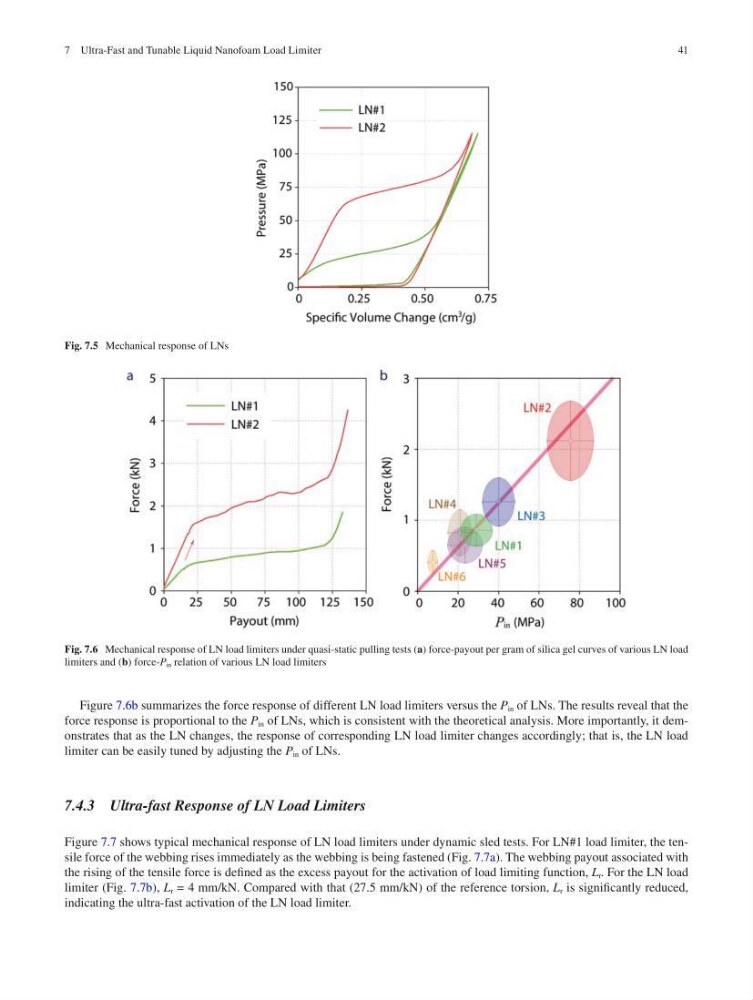
Fig. 7.5 Mechanical response of LNs
Fig. 7.6 Mechanical response of LN load limiters under quasi-static pulling tests (a) force-payout per gram of silica gel curves of various LN load
limiters and (b) force-P in relation of various LN load limiters
Figure 7.6b summarizes the force response of different LN load limiters versus the P in of LNs. The results reveal that the
force response is proportional to the P in of LNs, which is consistent with the theoretical analysis. More importantly, it demonstrates that as the LN changes, the response of corresponding LN load limiter changes accordingly; that is, the LN load
limiter can be easily tuned by adjusting the P in of LNs.
7.4.3 Ultra-fast Response of LN Load Limiters
Figure 7.7 shows typical mechanical response of LN load limiters under dynamic sled tests. For LN#1 load limiter, the tensile force of the webbing rises immediately as the webbing is being fastened (Fig. 7.7a). The webbing payout associated with
the rising of the tensile force is defined as the excess payout for the activation of load limiting function, L r . For the LN load
limiter (Fig. 7.7b), L r = 4 mm/kN. Compared with that (27.5 mm/kN) of the reference torsion, L r is significantly reduced,
indicating the ultra-fast activation of the LN load limiter.
7 Ultra-Fast and Tunable Liquid Nanofoam Load Limiter
Fig. 7.5 Mechanical response of LNs
Fig. 7.6 Mechanical response of LN load limiters under quasi-static pulling tests (a) force-payout per gram of silica gel curves of various LN load
limiters and (b) force-P in relation of various LN load limiters
Figure 7.6b summarizes the force response of different LN load limiters versus the P in of LNs. The results reveal that the
force response is proportional to the P in of LNs, which is consistent with the theoretical analysis. More importantly, it demonstrates that as the LN changes, the response of corresponding LN load limiter changes accordingly; that is, the LN load
limiter can be easily tuned by adjusting the P in of LNs.
7.4.3 Ultra-fast Response of LN Load Limiters
Figure 7.7 shows typical mechanical response of LN load limiters under dynamic sled tests. For LN#1 load limiter, the tensile force of the webbing rises immediately as the webbing is being fastened (Fig. 7.7a). The webbing payout associated with
the rising of the tensile force is defined as the excess payout for the activation of load limiting function, L r . For the LN load
limiter (Fig. 7.7b), L r = 4 mm/kN. Compared with that (27.5 mm/kN) of the reference torsion, L r is significantly reduced,
indicating the ultra-fast activation of the LN load limiter.
7 Ultra-Fast and Tunable Liquid Nanofoam Load Limiter