

114
6 Nonlinear Analysis of Piezoceramic Laminated Structures
(a)
0
0.05
0.1
0.15
0
0.1
0.2
0.3
0.4
0.5
0.6
0.7
0.8
Time (s)
Displacement (m)
LRT56 (SH851URI, mesh 10X1)
LRT5 (SH851URI, mesh 10X1)
MRT5 (SH851URI, mesh 10X1)
RVK5 (SH851URI, mesh 10X1)
Linear (SH851URI, mesh 10X1)
(b)
0
0.05
0.1
0.15
0
500
1000
1500
2000
2500
Time (s)
Voltage (V)
LRT56 (SH851URI, mesh 10X1)
LRT5 (SH851URI, mesh 10X1)
MRT5 (SH851URI, mesh 10X1)
RVK5 (SH851URI, mesh 10X1)
Linear (SH851URI, mesh 10X1)
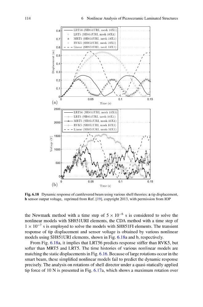
Fig. 6.18 Dynamic response of cantilevered beam using various shell theories: a tip displacement,
b sensor output voltage, reprinted from Ref. [19], copyright 2013, with permission from IOP
the Newmark method with a time step of 5 × 10
−6 s is considered to solve the
nonlinear models with SH851URI elements, the CDA method with a time step of
1 × 10
−7 s is employed to solve the models with SH851FI elements. The transient
response of tip displacement and sensor voltage is obtained by various nonlinear
models using SH851URI elements, shown in Fig. 6.18a and b, respectively.
From Fig. 6.18a, it implies that LRT56 predicts response stiffer than RVK5, but
softer than MRT5 and LRT5. The time histories of various nonlinear models are
matching the static displacements in Fig. 6.16. Because of large rotations occur in the
smart beam, these simplified nonlinear models fail to predict the dynamic response
precisely. The analysis on rotations of shell director under a quasi-statically applied
tip force of 10 N is presented in Fig. 6.17a, which shows a maximum rotation over
6 Nonlinear Analysis of Piezoceramic Laminated Structures
(a)
0
0.05
0.1
0.15
0
0.1
0.2
0.3
0.4
0.5
0.6
0.7
0.8
Time (s)
Displacement (m)
LRT56 (SH851URI, mesh 10X1)
LRT5 (SH851URI, mesh 10X1)
MRT5 (SH851URI, mesh 10X1)
RVK5 (SH851URI, mesh 10X1)
Linear (SH851URI, mesh 10X1)
(b)
0
0.05
0.1
0.15
0
500
1000
1500
2000
2500
Time (s)
Voltage (V)
LRT56 (SH851URI, mesh 10X1)
LRT5 (SH851URI, mesh 10X1)
MRT5 (SH851URI, mesh 10X1)
RVK5 (SH851URI, mesh 10X1)
Linear (SH851URI, mesh 10X1)
Fig. 6.18 Dynamic response of cantilevered beam using various shell theories: a tip displacement,
b sensor output voltage, reprinted from Ref. [19], copyright 2013, with permission from IOP
the Newmark method with a time step of 5 × 10
−6 s is considered to solve the
nonlinear models with SH851URI elements, the CDA method with a time step of
1 × 10
−7 s is employed to solve the models with SH851FI elements. The transient
response of tip displacement and sensor voltage is obtained by various nonlinear
models using SH851URI elements, shown in Fig. 6.18a and b, respectively.
From Fig. 6.18a, it implies that LRT56 predicts response stiffer than RVK5, but
softer than MRT5 and LRT5. The time histories of various nonlinear models are
matching the static displacements in Fig. 6.16. Because of large rotations occur in the
smart beam, these simplified nonlinear models fail to predict the dynamic response
precisely. The analysis on rotations of shell director under a quasi-statically applied
tip force of 10 N is presented in Fig. 6.17a, which shows a maximum rotation over