

6.2 Buckling and Post-buckling Analysis
107
0
1
2
3
4
5
6
7
8
0
50
100
150
200
250
Radial displacement (in)
Force P (lb)
LRT56
(12x12 SH851URI)
Stander, 1989
Sansour, 1995
Kreja, 2006
Sze, 2004
ANSYS
(12x12 SHELL281)
Outward
Inward
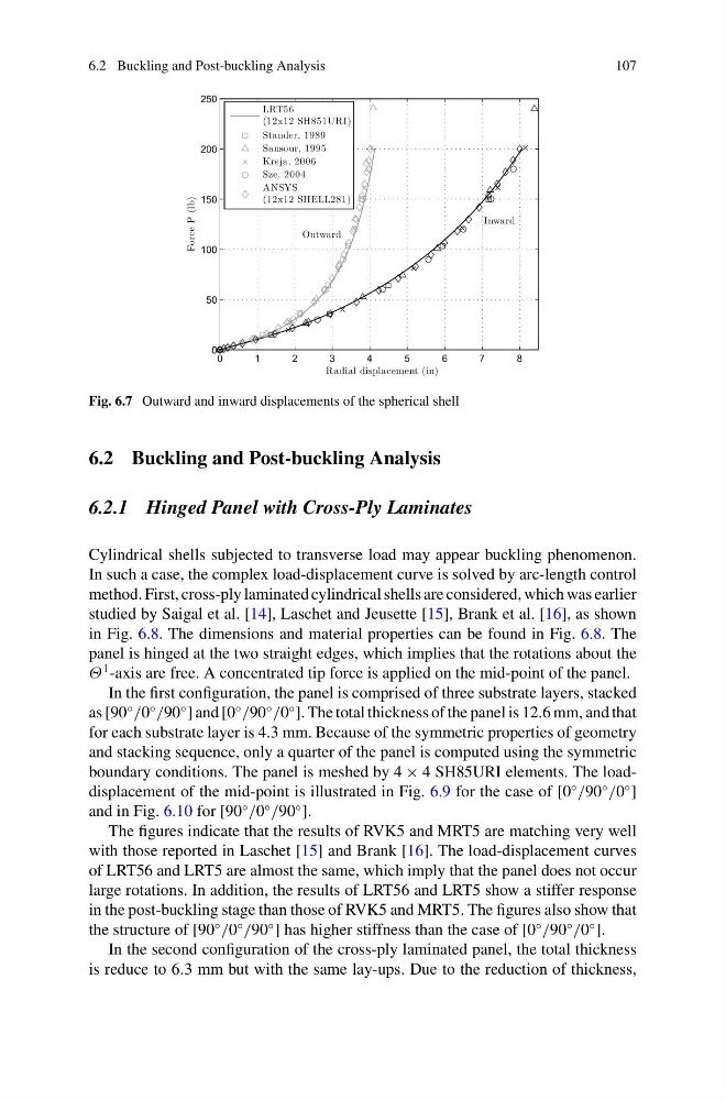
Fig. 6.7 Outward and inward displacements of the spherical shell
6.2 Buckling and Post-buckling Analysis
6.2.1 Hinged Panel with Cross-Ply Laminates
Cylindrical shells subjected to transverse load may appear buckling phenomenon.
In such a case, the complex load-displacement curve is solved by arc-length control
method. First, cross-ply laminated cylindrical shells are considered, which was earlier
studied by Saigal et al. [14], Laschet and Jeusette [15], Brank et al. [16], as shown
in Fig. 6.8. The dimensions and material properties can be found in Fig. 6.8. The
panel is hinged at the two straight edges, which implies that the rotations about the
Θ
1 -axis are free. A concentrated tip force is applied on the mid-point of the panel.
In the first configuration, the panel is comprised of three substrate layers, stacked
as [90
◦
/0
◦
/90
◦
] and [0
◦
/90
◦
/0
◦
]. The total thickness of the panel is 12.6 mm, and that
for each substrate layer is 4.3 mm. Because of the symmetric properties of geometry
and stacking sequence, only a quarter of the panel is computed using the symmetric
boundary conditions. The panel is meshed by 4 × 4 SH85URI elements. The loaddisplacement of the mid-point is illustrated in Fig. 6.9 for the case of [0
◦
/90
◦
/0
◦
]
and in Fig. 6.10 for [90
◦
/0
◦
/90
◦
].
The figures indicate that the results of RVK5 and MRT5 are matching very well
with those reported in Laschet [15] and Brank [16]. The load-displacement curves
of LRT56 and LRT5 are almost the same, which imply that the panel does not occur
large rotations. In addition, the results of LRT56 and LRT5 show a stiffer response
in the post-buckling stage than those of RVK5 and MRT5. The figures also show that
the structure of [90
◦
/0
◦
/90
◦
] has higher stiffness than the case of [0
◦
/90
◦
/0
◦
].
In the second configuration of the cross-ply laminated panel, the total thickness
is reduce to 6.3 mm but with the same lay-ups. Due to the reduction of thickness,
107
0
1
2
3
4
5
6
7
8
0
50
100
150
200
250
Radial displacement (in)
Force P (lb)
LRT56
(12x12 SH851URI)
Stander, 1989
Sansour, 1995
Kreja, 2006
Sze, 2004
ANSYS
(12x12 SHELL281)
Outward
Inward
Fig. 6.7 Outward and inward displacements of the spherical shell
6.2 Buckling and Post-buckling Analysis
6.2.1 Hinged Panel with Cross-Ply Laminates
Cylindrical shells subjected to transverse load may appear buckling phenomenon.
In such a case, the complex load-displacement curve is solved by arc-length control
method. First, cross-ply laminated cylindrical shells are considered, which was earlier
studied by Saigal et al. [14], Laschet and Jeusette [15], Brank et al. [16], as shown
in Fig. 6.8. The dimensions and material properties can be found in Fig. 6.8. The
panel is hinged at the two straight edges, which implies that the rotations about the
Θ
1 -axis are free. A concentrated tip force is applied on the mid-point of the panel.
In the first configuration, the panel is comprised of three substrate layers, stacked
as [90
◦
/0
◦
/90
◦
] and [0
◦
/90
◦
/0
◦
]. The total thickness of the panel is 12.6 mm, and that
for each substrate layer is 4.3 mm. Because of the symmetric properties of geometry
and stacking sequence, only a quarter of the panel is computed using the symmetric
boundary conditions. The panel is meshed by 4 × 4 SH85URI elements. The loaddisplacement of the mid-point is illustrated in Fig. 6.9 for the case of [0
◦
/90
◦
/0
◦
]
and in Fig. 6.10 for [90
◦
/0
◦
/90
◦
].
The figures indicate that the results of RVK5 and MRT5 are matching very well
with those reported in Laschet [15] and Brank [16]. The load-displacement curves
of LRT56 and LRT5 are almost the same, which imply that the panel does not occur
large rotations. In addition, the results of LRT56 and LRT5 show a stiffer response
in the post-buckling stage than those of RVK5 and MRT5. The figures also show that
the structure of [90
◦
/0
◦
/90
◦
] has higher stiffness than the case of [0
◦
/90
◦
/0
◦
].
In the second configuration of the cross-ply laminated panel, the total thickness
is reduce to 6.3 mm but with the same lay-ups. Due to the reduction of thickness,