

106
6 Nonlinear Analysis of Piezoceramic Laminated Structures
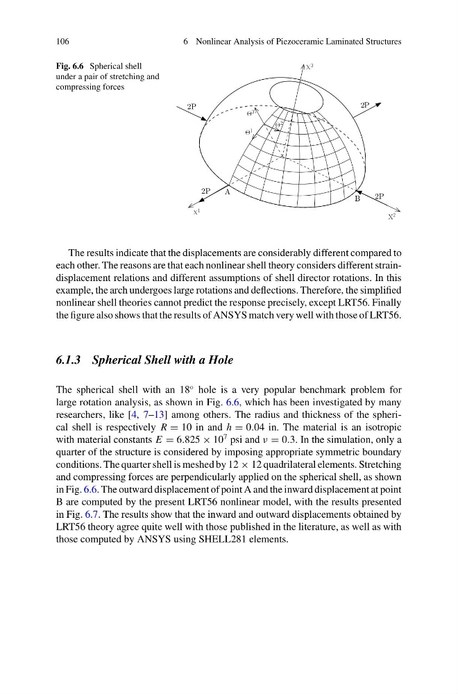
Fig. 6.6 Spherical shell
under a pair of stretching and
compressing forces
2P
X 1
2P
X 3
Θ 1
Θ 2
Θ 3
2P
X 2
A
B
2P
The results indicate that the displacements are considerably different compared to
each other. The reasons are that each nonlinear shell theory considers different straindisplacement relations and different assumptions of shell director rotations. In this
example, the arch undergoes large rotations and deflections. Therefore, the simplified
nonlinear shell theories cannot predict the response precisely, except LRT56. Finally
the figure also shows that the results of ANSYS match very well with those of LRT56.
6.1.3 Spherical Shell with a Hole
The spherical shell with an 18
◦ hole is a very popular benchmark problem for
large rotation analysis, as shown in Fig. 6.6, which has been investigated by many
researchers, like [4, 7–13] among others. The radius and thickness of the spherical shell is respectively R = 10 in and h = 0.04 in. The material is an isotropic
with material constants E = 6.825 × 10
7 psi and ν = 0.3. In the simulation, only a
quarter of the structure is considered by imposing appropriate symmetric boundary
conditions. The quarter shell is meshed by 12 × 12 quadrilateral elements. Stretching
and compressing forces are perpendicularly applied on the spherical shell, as shown
in Fig. 6.6. The outward displacement of point A and the inward displacement at point
B are computed by the present LRT56 nonlinear model, with the results presented
in Fig. 6.7. The results show that the inward and outward displacements obtained by
LRT56 theory agree quite well with those published in the literature, as well as with
those computed by ANSYS using SHELL281 elements.
6 Nonlinear Analysis of Piezoceramic Laminated Structures
Fig. 6.6 Spherical shell
under a pair of stretching and
compressing forces
2P
X 1
2P
X 3
Θ 1
Θ 2
Θ 3
2P
X 2
A
B
2P
The results indicate that the displacements are considerably different compared to
each other. The reasons are that each nonlinear shell theory considers different straindisplacement relations and different assumptions of shell director rotations. In this
example, the arch undergoes large rotations and deflections. Therefore, the simplified
nonlinear shell theories cannot predict the response precisely, except LRT56. Finally
the figure also shows that the results of ANSYS match very well with those of LRT56.
6.1.3 Spherical Shell with a Hole
The spherical shell with an 18
◦ hole is a very popular benchmark problem for
large rotation analysis, as shown in Fig. 6.6, which has been investigated by many
researchers, like [4, 7–13] among others. The radius and thickness of the spherical shell is respectively R = 10 in and h = 0.04 in. The material is an isotropic
with material constants E = 6.825 × 10
7 psi and ν = 0.3. In the simulation, only a
quarter of the structure is considered by imposing appropriate symmetric boundary
conditions. The quarter shell is meshed by 12 × 12 quadrilateral elements. Stretching
and compressing forces are perpendicularly applied on the spherical shell, as shown
in Fig. 6.6. The outward displacement of point A and the inward displacement at point
B are computed by the present LRT56 nonlinear model, with the results presented
in Fig. 6.7. The results show that the inward and outward displacements obtained by
LRT56 theory agree quite well with those published in the literature, as well as with
those computed by ANSYS using SHELL281 elements.