

318
P. Liu
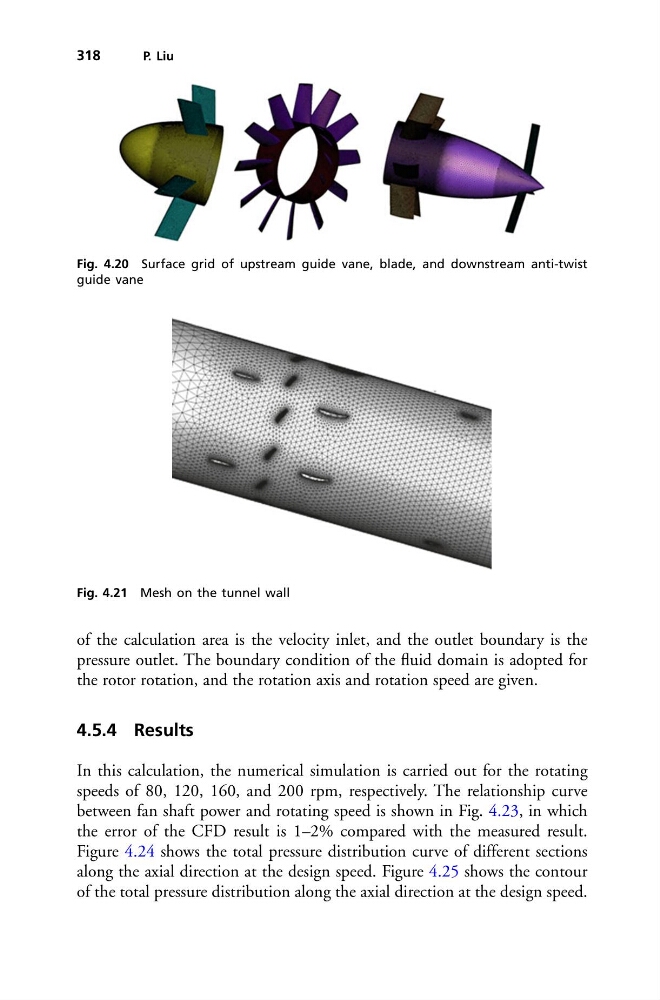
Fig. 4.20 Surface grid of upstream guide vane, blade, and downstream anti-twist
guide vane
Fig. 4.21 Mesh on the tunnel wall
of the calculation area is the velocity inlet, and the outlet boundary is the
pressure outlet. The boundary condition of the fluid domain is adopted for
the rotor rotation, and the rotation axis and rotation speed are given.
4.5.4 Results
In this calculation, the numerical simulation is carried out for the rotating
speeds of 80, 120, 160, and 200 rpm, respectively. The relationship curve
between fan shaft power and rotating speed is shown in Fig. 4.23, in which
the error of the CFD result is 1–2% compared with the measured result.
Figure 4.24 shows the total pressure distribution curve of different sections
along the axial direction at the design speed. Figure 4.25 shows the contour
of the total pressure distribution along the axial direction at the design speed.
P. Liu
Fig. 4.20 Surface grid of upstream guide vane, blade, and downstream anti-twist
guide vane
Fig. 4.21 Mesh on the tunnel wall
of the calculation area is the velocity inlet, and the outlet boundary is the
pressure outlet. The boundary condition of the fluid domain is adopted for
the rotor rotation, and the rotation axis and rotation speed are given.
4.5.4 Results
In this calculation, the numerical simulation is carried out for the rotating
speeds of 80, 120, 160, and 200 rpm, respectively. The relationship curve
between fan shaft power and rotating speed is shown in Fig. 4.23, in which
the error of the CFD result is 1–2% compared with the measured result.
Figure 4.24 shows the total pressure distribution curve of different sections
along the axial direction at the design speed. Figure 4.25 shows the contour
of the total pressure distribution along the axial direction at the design speed.