

4 Computational Fluid Dynamics
317
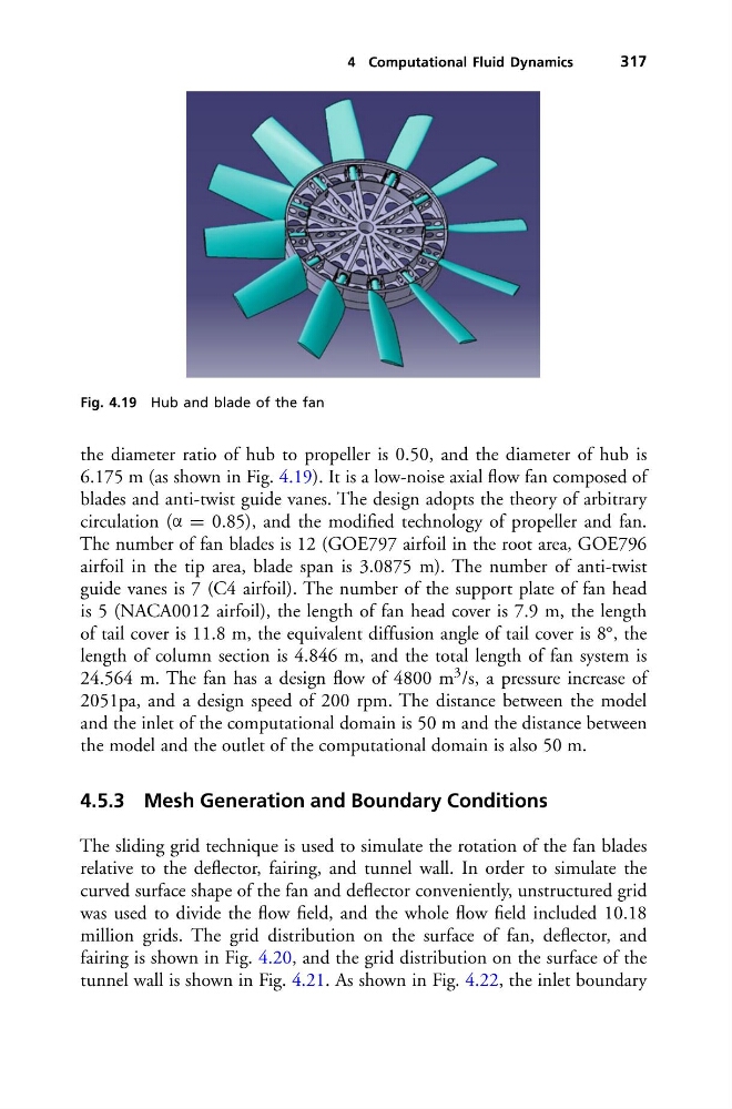
Fig. 4.19 Hub and blade of the fan
the diameter ratio of hub to propeller is 0.50, and the diameter of hub is
6.175 m (as shown in Fig. 4.19). It is a low-noise axial flow fan composed of
blades and anti-twist guide vanes. The design adopts the theory of arbitrary
circulation (α = 0.85), and the modified technology of propeller and fan.
The number of fan blades is 12 (GOE797 airfoil in the root area, GOE796
airfoil in the tip area, blade span is 3.0875 m). The number of anti-twist
guide vanes is 7 (C4 airfoil). The number of the support plate of fan head
is 5 (NACA0012 airfoil), the length of fan head cover is 7.9 m, the length
of tail cover is 11.8 m, the equivalent diffusion angle of tail cover is 8°, the
length of column section is 4.846 m, and the total length of fan system is
24.564 m. The fan has a design flow of 4800 m 3 /s, a pressure increase of
2051pa, and a design speed of 200 rpm. The distance between the model
and the inlet of the computational domain is 50 m and the distance between
the model and the outlet of the computational domain is also 50 m.
4.5.3 Mesh Generation and Boundary Conditions
The sliding grid technique is used to simulate the rotation of the fan blades
relative to the deflector, fairing, and tunnel wall. In order to simulate the
curved surface shape of the fan and deflector conveniently, unstructured grid
was used to divide the flow field, and the whole flow field included 10.18
million grids. The grid distribution on the surface of fan, deflector, and
fairing is shown in Fig. 4.20, and the grid distribution on the surface of the
tunnel wall is shown in Fig. 4.21. As shown in Fig. 4.22, the inlet boundary
317
Fig. 4.19 Hub and blade of the fan
the diameter ratio of hub to propeller is 0.50, and the diameter of hub is
6.175 m (as shown in Fig. 4.19). It is a low-noise axial flow fan composed of
blades and anti-twist guide vanes. The design adopts the theory of arbitrary
circulation (α = 0.85), and the modified technology of propeller and fan.
The number of fan blades is 12 (GOE797 airfoil in the root area, GOE796
airfoil in the tip area, blade span is 3.0875 m). The number of anti-twist
guide vanes is 7 (C4 airfoil). The number of the support plate of fan head
is 5 (NACA0012 airfoil), the length of fan head cover is 7.9 m, the length
of tail cover is 11.8 m, the equivalent diffusion angle of tail cover is 8°, the
length of column section is 4.846 m, and the total length of fan system is
24.564 m. The fan has a design flow of 4800 m 3 /s, a pressure increase of
2051pa, and a design speed of 200 rpm. The distance between the model
and the inlet of the computational domain is 50 m and the distance between
the model and the outlet of the computational domain is also 50 m.
4.5.3 Mesh Generation and Boundary Conditions
The sliding grid technique is used to simulate the rotation of the fan blades
relative to the deflector, fairing, and tunnel wall. In order to simulate the
curved surface shape of the fan and deflector conveniently, unstructured grid
was used to divide the flow field, and the whole flow field included 10.18
million grids. The grid distribution on the surface of fan, deflector, and
fairing is shown in Fig. 4.20, and the grid distribution on the surface of the
tunnel wall is shown in Fig. 4.21. As shown in Fig. 4.22, the inlet boundary