

4 Computational Fluid Dynamics
319
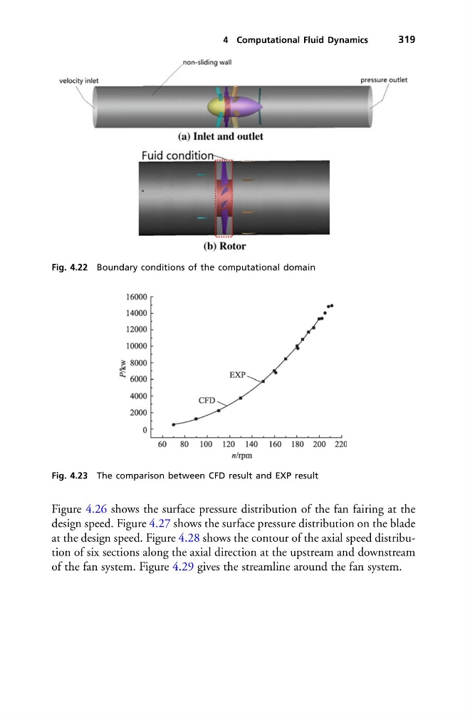
Fig. 4.22 Boundary conditions of the computational domain
Fig. 4.23 The comparison between CFD result and EXP result
Figure 4.26 shows the surface pressure distribution of the fan fairing at the
design speed. Figure 4.27 shows the surface pressure distribution on the blade
at the design speed. Figure 4.28 shows the contour of the axial speed distribution of six sections along the axial direction at the upstream and downstream
of the fan system. Figure 4.29 gives the streamline around the fan system.
319
Fig. 4.22 Boundary conditions of the computational domain
Fig. 4.23 The comparison between CFD result and EXP result
Figure 4.26 shows the surface pressure distribution of the fan fairing at the
design speed. Figure 4.27 shows the surface pressure distribution on the blade
at the design speed. Figure 4.28 shows the contour of the axial speed distribution of six sections along the axial direction at the upstream and downstream
of the fan system. Figure 4.29 gives the streamline around the fan system.