

include considerations of statistics (Fisher, 1953)
have advantages over these contouring methods,
so examples are presented after we describe how
to prepare the fabric diagram.
The first step in the preparation of the fabric
diagram is the plotting of points that represent
the orientations of line elements (e.g. the normals
to foliations or the lineations) on the Schmidt net.
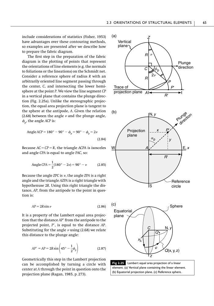
Consider a reference sphere of radius R with an
arbitrarily oriented line segment passing through
the center, C, and intersecting the lower hemisphere at the point P. We view the line segment CP
in a vertical plane that contains the plunge direction (Fig. 2.25a). Unlike the stereographic projection, the equal area projection plane is tangent to
the sphere at the antipode, A. Given the relation
(2.68) between the angle and the plunge angle,
p , the angle ACP is:
(2.84)
Because AC ϭ CP ϭ R, the triangle ACPA is isosceles
and angle CPA is equal to angle PAC, so:
(2.85)
Because the angle ZPC is , the angle ZPA is a right
angle and the triangle AZPA is a right triangle with
hypothenuse 2R. Using this right triangle the distance, AP, from the antipode to the point in question is:
(2.86)
It is a property of the Lambert equal area projection that the distance APЈ from the antipode to the
projected point, PЈ, is equal to the distance AP.
Substituting for the angle using (2.68) we relate
this distance to the plunge angle:
(2.87)
Geometrically this step in the Lambert projection
can be accomplished by turning a circle with
center at A through the point in question onto the
projection plane (Ragan, 1985, p. 273).
APЈ ϭ AP ϭ 2R sin 45° Ϫ
1
2
p
AP ϭ 2R sin
Angle CPA ϭ
1
2
(180° Ϫ 2) ϭ 90° Ϫ
Angle ACP ϭ 180° Ϫ 90° Ϫ p ϭ 90° Ϫ p ϭ 2
2.3 ORIENTATIONS OF STRUCTURAL ELEMENTS
65
Fig 2.25 Lambert equal area projection of a linear
element. (a) Vertical plane containing the linear element.
(b) Equatorial projection plane. (c) Reference sphere.
(c)
x l
N, y
Sphere
C
z
w
QЈ
Equatorial
plane
Q(x, y, z)
(a)
Z
C
PЈ
P
R
R
A
RЈ
2n
n
Vertical
plane
Plunge
direction
f p
Trace of
projection plane
(b)
W
E, x
N, y
S
A
PЈ
x
y
RЈ
P l u n g e
d i r e c t i o n
Projection
plane
a p
Reference
circle
have advantages over these contouring methods,
so examples are presented after we describe how
to prepare the fabric diagram.
The first step in the preparation of the fabric
diagram is the plotting of points that represent
the orientations of line elements (e.g. the normals
to foliations or the lineations) on the Schmidt net.
Consider a reference sphere of radius R with an
arbitrarily oriented line segment passing through
the center, C, and intersecting the lower hemisphere at the point P. We view the line segment CP
in a vertical plane that contains the plunge direction (Fig. 2.25a). Unlike the stereographic projection, the equal area projection plane is tangent to
the sphere at the antipode, A. Given the relation
(2.68) between the angle and the plunge angle,
p , the angle ACP is:
(2.84)
Because AC ϭ CP ϭ R, the triangle ACPA is isosceles
and angle CPA is equal to angle PAC, so:
(2.85)
Because the angle ZPC is , the angle ZPA is a right
angle and the triangle AZPA is a right triangle with
hypothenuse 2R. Using this right triangle the distance, AP, from the antipode to the point in question is:
(2.86)
It is a property of the Lambert equal area projection that the distance APЈ from the antipode to the
projected point, PЈ, is equal to the distance AP.
Substituting for the angle using (2.68) we relate
this distance to the plunge angle:
(2.87)
Geometrically this step in the Lambert projection
can be accomplished by turning a circle with
center at A through the point in question onto the
projection plane (Ragan, 1985, p. 273).
APЈ ϭ AP ϭ 2R sin 45° Ϫ
1
2
p
AP ϭ 2R sin
Angle CPA ϭ
1
2
(180° Ϫ 2) ϭ 90° Ϫ
Angle ACP ϭ 180° Ϫ 90° Ϫ p ϭ 90° Ϫ p ϭ 2
2.3 ORIENTATIONS OF STRUCTURAL ELEMENTS
65
Fig 2.25 Lambert equal area projection of a linear
element. (a) Vertical plane containing the linear element.
(b) Equatorial projection plane. (c) Reference sphere.
(c)
x l
N, y
Sphere
C
z
w
QЈ
Equatorial
plane
Q(x, y, z)
(a)
Z
C
PЈ
P
R
R
A
RЈ
2n
n
Vertical
plane
Plunge
direction
f p
Trace of
projection plane
(b)
W
E, x
N, y
S
A
PЈ
x
y
RЈ
P l u n g e
d i r e c t i o n
Projection
plane
a p
Reference
circle