

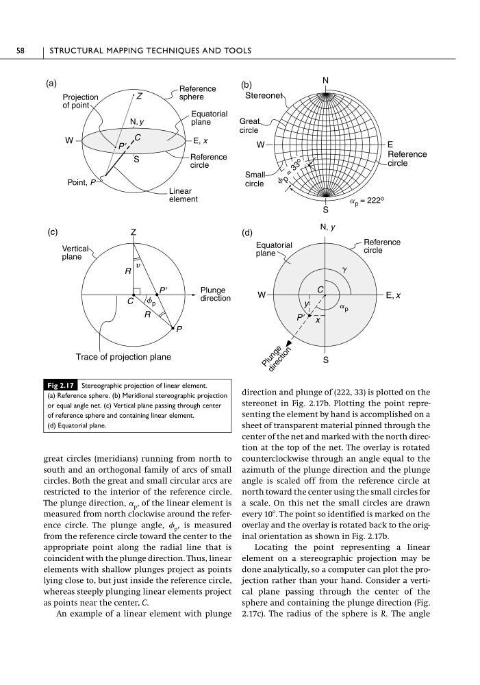
great circles (meridians) running from north to
south and an orthogonal family of arcs of small
circles. Both the great and small circular arcs are
restricted to the interior of the reference circle.
The plunge direction, ␣ p , of the linear element is
measured from north clockwise around the reference circle. The plunge angle, p , is measured
from the reference circle toward the center to the
appropriate point along the radial line that is
coincident with the plunge direction. Thus, linear
elements with shallow plunges project as points
lying close to, but just inside the reference circle,
whereas steeply plunging linear elements project
as points near the center, C.
An example of a linear element with plunge
direction and plunge of (222, 33) is plotted on the
stereonet in Fig. 2.17b. Plotting the point representing the element by hand is accomplished on a
sheet of transparent material pinned through the
center of the net and marked with the north direction at the top of the net. The overlay is rotated
counterclockwise through an angle equal to the
azimuth of the plunge direction and the plunge
angle is scaled off from the reference circle at
north toward the center using the small circles for
a scale. On this net the small circles are drawn
every 10Њ. The point so identified is marked on the
overlay and the overlay is rotated back to the original orientation as shown in Fig. 2.17b.
Locating the point representing a linear
element on a stereographic projection may be
done analytically, so a computer can plot the projection rather than your hand. Consider a vertical plane passing through the center of the
sphere and containing the plunge direction (Fig.
2.17c). The radius of the sphere is R. The angle
58
STRUCTURAL MAPPING TECHNIQUES AND TOOLS
(a)
W
S
(c)
N
W
S
E
Stereonet
(b)
Z
Z
P Ј
C
F p
Trace of projection plane
C
P Ј
(d)
W
S
C
P Ј
P
y
R
R
x
y
g
Reference
circle
Projection
of point
Reference
sphere
Equatorial
plane
E, x
Reference
circle
Linear
element
Point, P
Great
circle
Small
circle
Vertical
plane
Plunge
direction
Equatorial
plane
Reference
circle
P l u n g e
d i r e c t i o n
a p = 222 o
F p
=
3 3
o
N, y
N, y
a p
E, x
Fig 2.17 Stereographic projection of linear element.
(a) Reference sphere. (b) Meridional stereographic projection
or equal angle net. (c) Vertical plane passing through center
of reference sphere and containing linear element.
(d) Equatorial plane.
south and an orthogonal family of arcs of small
circles. Both the great and small circular arcs are
restricted to the interior of the reference circle.
The plunge direction, ␣ p , of the linear element is
measured from north clockwise around the reference circle. The plunge angle, p , is measured
from the reference circle toward the center to the
appropriate point along the radial line that is
coincident with the plunge direction. Thus, linear
elements with shallow plunges project as points
lying close to, but just inside the reference circle,
whereas steeply plunging linear elements project
as points near the center, C.
An example of a linear element with plunge
direction and plunge of (222, 33) is plotted on the
stereonet in Fig. 2.17b. Plotting the point representing the element by hand is accomplished on a
sheet of transparent material pinned through the
center of the net and marked with the north direction at the top of the net. The overlay is rotated
counterclockwise through an angle equal to the
azimuth of the plunge direction and the plunge
angle is scaled off from the reference circle at
north toward the center using the small circles for
a scale. On this net the small circles are drawn
every 10Њ. The point so identified is marked on the
overlay and the overlay is rotated back to the original orientation as shown in Fig. 2.17b.
Locating the point representing a linear
element on a stereographic projection may be
done analytically, so a computer can plot the projection rather than your hand. Consider a vertical plane passing through the center of the
sphere and containing the plunge direction (Fig.
2.17c). The radius of the sphere is R. The angle
58
STRUCTURAL MAPPING TECHNIQUES AND TOOLS
(a)
W
S
(c)
N
W
S
E
Stereonet
(b)
Z
Z
P Ј
C
F p
Trace of projection plane
C
P Ј
(d)
W
S
C
P Ј
P
y
R
R
x
y
g
Reference
circle
Projection
of point
Reference
sphere
Equatorial
plane
E, x
Reference
circle
Linear
element
Point, P
Great
circle
Small
circle
Vertical
plane
Plunge
direction
Equatorial
plane
Reference
circle
P l u n g e
d i r e c t i o n
a p = 222 o
F p
=
3 3
o
N, y
N, y
a p
E, x
Fig 2.17 Stereographic projection of linear element.
(a) Reference sphere. (b) Meridional stereographic projection
or equal angle net. (c) Vertical plane passing through center
of reference sphere and containing linear element.
(d) Equatorial plane.