

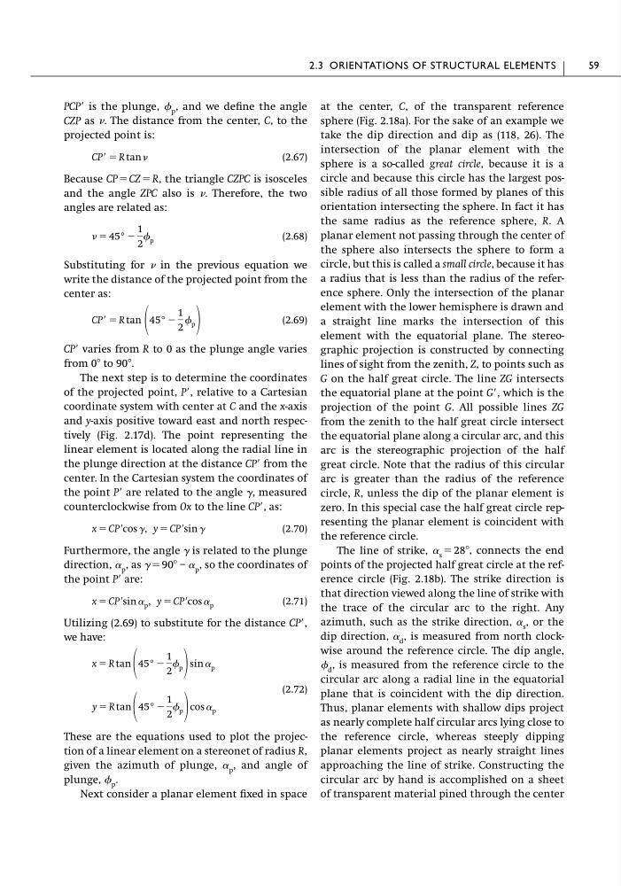
PCPЈ is the plunge, p , and we define the angle
CZP as . The distance from the center, C, to the
projected point is:
(2.67)
Because CP ϭ CZ ϭ R, the triangle CZPC is isosceles
and the angle ZPC also is . Therefore, the two
angles are related as:
(2.68)
Substituting for in the previous equation we
write the distance of the projected point from the
center as:
(2.69)
CPЈ varies from R to 0 as the plunge angle varies
from 0Њ to 90Њ.
The next step is to determine the coordinates
of the projected point, PЈ, relative to a Cartesian
coordinate system with center at C and the x-axis
and y-axis positive toward east and north respectively (Fig. 2.17d). The point representing the
linear element is located along the radial line in
the plunge direction at the distance CPЈ from the
center. In the Cartesian system the coordinates of
the point PЈ are related to the angle ␥, measured
counterclockwise from Ox to the line CPЈ, as:
(2.70)
Furthermore, the angle ␥ is related to the plunge
direction, ␣ p , as ␥ ϭ 90Њ – ␣ p , so the coordinates of
the point PЈ are:
(2.71)
Utilizing (2.69) to substitute for the distance CPЈ,
we have:
(2.72)
These are the equations used to plot the projection of a linear element on a stereonet of radius R,
given the azimuth of plunge, ␣ p , and angle of
plunge, p .
Next consider a planar element fixed in space
y ϭ R tan 45° Ϫ
1
2
p cos ␣ p
x ϭ R tan 45° Ϫ
1
2
p sin ␣ p
x ϭ CPЈ sin ␣ p , y ϭ CPЈ cos ␣ p
x ϭ CPЈ cos ␥, y ϭ CPЈ sin ␥
CPЈ ϭ R tan 45° Ϫ
1
2
p
ϭ 45° Ϫ
1
2
p
CPЈ ϭ R tan
at the center, C, of the transparent reference
sphere (Fig. 2.18a). For the sake of an example we
take the dip direction and dip as (118, 26). The
intersection of the planar element with the
sphere is a so-called great circle, because it is a
circle and because this circle has the largest possible radius of all those formed by planes of this
orientation intersecting the sphere. In fact it has
the same radius as the reference sphere, R. A
planar element not passing through the center of
the sphere also intersects the sphere to form a
circle, but this is called a small circle, because it has
a radius that is less than the radius of the reference sphere. Only the intersection of the planar
element with the lower hemisphere is drawn and
a straight line marks the intersection of this
element with the equatorial plane. The stereographic projection is constructed by connecting
lines of sight from the zenith, Z, to points such as
G on the half great circle. The line ZG intersects
the equatorial plane at the point GЈ, which is the
projection of the point G. All possible lines ZG
from the zenith to the half great circle intersect
the equatorial plane along a circular arc, and this
arc is the stereographic projection of the half
great circle. Note that the radius of this circular
arc is greater than the radius of the reference
circle, R, unless the dip of the planar element is
zero. In this special case the half great circle representing the planar element is coincident with
the reference circle.
The line of strike, ␣ s ϭ 28Њ, connects the end
points of the projected half great circle at the reference circle (Fig. 2.18b). The strike direction is
that direction viewed along the line of strike with
the trace of the circular arc to the right. Any
azimuth, such as the strike direction, ␣ s , or the
dip direction, ␣ d , is measured from north clockwise around the reference circle. The dip angle,
d , is measured from the reference circle to the
circular arc along a radial line in the equatorial
plane that is coincident with the dip direction.
Thus, planar elements with shallow dips project
as nearly complete half circular arcs lying close to
the reference circle, whereas steeply dipping
planar elements project as nearly straight lines
approaching the line of strike. Constructing the
circular arc by hand is accomplished on a sheet
of transparent material pined through the center
2.3 ORIENTATIONS OF STRUCTURAL ELEMENTS
59
CZP as . The distance from the center, C, to the
projected point is:
(2.67)
Because CP ϭ CZ ϭ R, the triangle CZPC is isosceles
and the angle ZPC also is . Therefore, the two
angles are related as:
(2.68)
Substituting for in the previous equation we
write the distance of the projected point from the
center as:
(2.69)
CPЈ varies from R to 0 as the plunge angle varies
from 0Њ to 90Њ.
The next step is to determine the coordinates
of the projected point, PЈ, relative to a Cartesian
coordinate system with center at C and the x-axis
and y-axis positive toward east and north respectively (Fig. 2.17d). The point representing the
linear element is located along the radial line in
the plunge direction at the distance CPЈ from the
center. In the Cartesian system the coordinates of
the point PЈ are related to the angle ␥, measured
counterclockwise from Ox to the line CPЈ, as:
(2.70)
Furthermore, the angle ␥ is related to the plunge
direction, ␣ p , as ␥ ϭ 90Њ – ␣ p , so the coordinates of
the point PЈ are:
(2.71)
Utilizing (2.69) to substitute for the distance CPЈ,
we have:
(2.72)
These are the equations used to plot the projection of a linear element on a stereonet of radius R,
given the azimuth of plunge, ␣ p , and angle of
plunge, p .
Next consider a planar element fixed in space
y ϭ R tan 45° Ϫ
1
2
p cos ␣ p
x ϭ R tan 45° Ϫ
1
2
p sin ␣ p
x ϭ CPЈ sin ␣ p , y ϭ CPЈ cos ␣ p
x ϭ CPЈ cos ␥, y ϭ CPЈ sin ␥
CPЈ ϭ R tan 45° Ϫ
1
2
p
ϭ 45° Ϫ
1
2
p
CPЈ ϭ R tan
at the center, C, of the transparent reference
sphere (Fig. 2.18a). For the sake of an example we
take the dip direction and dip as (118, 26). The
intersection of the planar element with the
sphere is a so-called great circle, because it is a
circle and because this circle has the largest possible radius of all those formed by planes of this
orientation intersecting the sphere. In fact it has
the same radius as the reference sphere, R. A
planar element not passing through the center of
the sphere also intersects the sphere to form a
circle, but this is called a small circle, because it has
a radius that is less than the radius of the reference sphere. Only the intersection of the planar
element with the lower hemisphere is drawn and
a straight line marks the intersection of this
element with the equatorial plane. The stereographic projection is constructed by connecting
lines of sight from the zenith, Z, to points such as
G on the half great circle. The line ZG intersects
the equatorial plane at the point GЈ, which is the
projection of the point G. All possible lines ZG
from the zenith to the half great circle intersect
the equatorial plane along a circular arc, and this
arc is the stereographic projection of the half
great circle. Note that the radius of this circular
arc is greater than the radius of the reference
circle, R, unless the dip of the planar element is
zero. In this special case the half great circle representing the planar element is coincident with
the reference circle.
The line of strike, ␣ s ϭ 28Њ, connects the end
points of the projected half great circle at the reference circle (Fig. 2.18b). The strike direction is
that direction viewed along the line of strike with
the trace of the circular arc to the right. Any
azimuth, such as the strike direction, ␣ s , or the
dip direction, ␣ d , is measured from north clockwise around the reference circle. The dip angle,
d , is measured from the reference circle to the
circular arc along a radial line in the equatorial
plane that is coincident with the dip direction.
Thus, planar elements with shallow dips project
as nearly complete half circular arcs lying close to
the reference circle, whereas steeply dipping
planar elements project as nearly straight lines
approaching the line of strike. Constructing the
circular arc by hand is accomplished on a sheet
of transparent material pined through the center
2.3 ORIENTATIONS OF STRUCTURAL ELEMENTS
59