

somewhat about the east–west axis, so the upper
surface of the equatorial plane inside the reference circle is visible as a shaded elliptical surface.
Thus, the zenith has moved toward the observer
and appears somewhat below what appears as the
top of the sphere. The zenith is chosen as the perspective point for the stereographic projections
described here. One also may choose the bottom
of the reference sphere as the perspective point.
The intersection of the linear element with the
lower hemisphere is a point, P, and this point is
projected to the point PЈ on the equatorial plane
along the line ZP from the zenith. By convention
only the intersection of the linear element with
the lower hemisphere is projected. The point
where the linear element would intersect the
upper hemisphere projects to a point on the equatorial plane that is outside the reference circle.
The scales for plotting the point representing
the linear element are provided by the meridional
stereographic net, sometimes called the Wulff net
after G. V. Wulff who published a version in 1902,
or the equal angle net, or the stereonet (Phillips,
1954). Later in this section we show how to construct the stereonet itself, but we start with a
simpler construction, which provides the technique for plotting linear elements. An example of
a stereonet is given in Fig. 2.17b where we note
that the net is composed of a family of arcs of
2.3 ORIENTATIONS OF STRUCTURAL ELEMENTS
57
40
90
63
90
72
D
75
U
31
10
10
90
70
30
90
Contact, showing dip
Contact, vertical (left) and
overturned (right)
Fault, showing dips
Fault, showing trend and plunge
of linear features (D, downthrown side; U, up-thrown side)
Fault, showing relative
horizontal movement
Thrust faults; T
or saw-teeth in upper plate
Normal fault;
hachures on down-thrown side
Anticline, showing trace of axial
plane and plunge of axis
Syncline, showing trace of axial
plane and plunge of axis
Strike and dip of bedding
Strike and dip of
overturned bedding
Strike of vertical bedding;
stratigraphic tops to north (right)
Horizontal bedding
Strike and dip of foliations
Strike of vertical foliations
Horizontal foliations
Strike and dip of joints
(left) and veins or dikes (right)
Strike of vertical joints (left)
and veins or dikes (right)
Horizontal joints
(left) and veins or dikes (right)
Trend and plunge of lineation
Vertical lineation
Trend of horizontal lineation
T
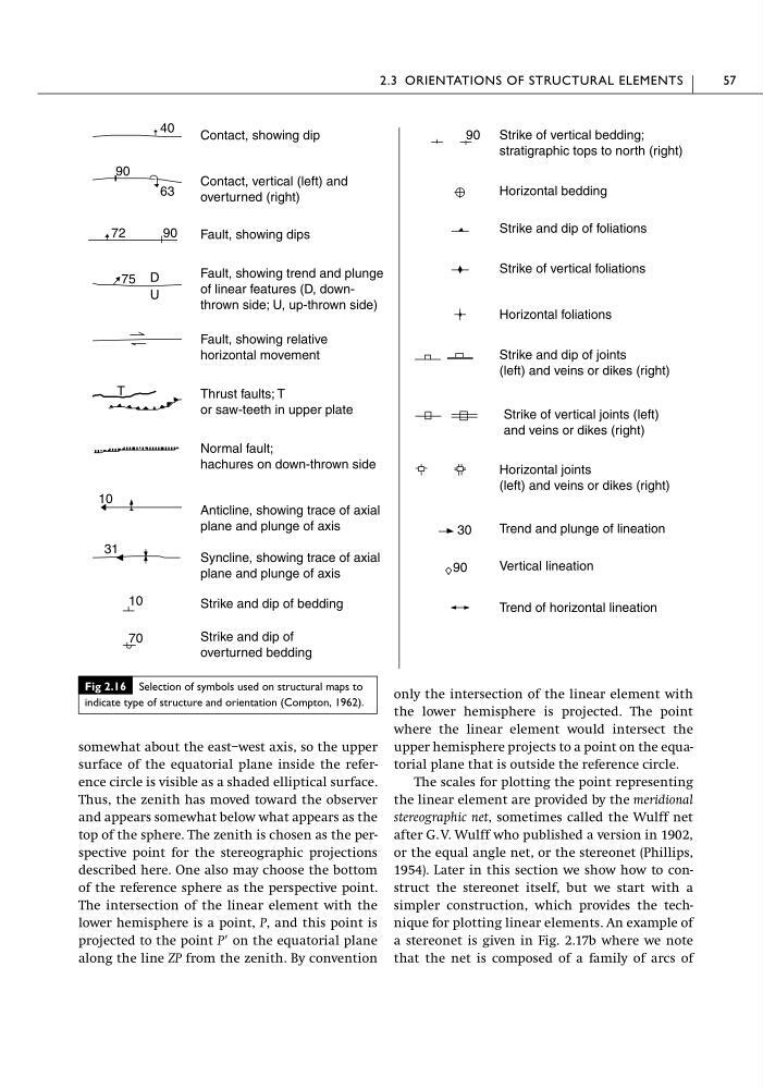
Fig 2.16 Selection of symbols used on structural maps to
indicate type of structure and orientation (Compton, 1962).
surface of the equatorial plane inside the reference circle is visible as a shaded elliptical surface.
Thus, the zenith has moved toward the observer
and appears somewhat below what appears as the
top of the sphere. The zenith is chosen as the perspective point for the stereographic projections
described here. One also may choose the bottom
of the reference sphere as the perspective point.
The intersection of the linear element with the
lower hemisphere is a point, P, and this point is
projected to the point PЈ on the equatorial plane
along the line ZP from the zenith. By convention
only the intersection of the linear element with
the lower hemisphere is projected. The point
where the linear element would intersect the
upper hemisphere projects to a point on the equatorial plane that is outside the reference circle.
The scales for plotting the point representing
the linear element are provided by the meridional
stereographic net, sometimes called the Wulff net
after G. V. Wulff who published a version in 1902,
or the equal angle net, or the stereonet (Phillips,
1954). Later in this section we show how to construct the stereonet itself, but we start with a
simpler construction, which provides the technique for plotting linear elements. An example of
a stereonet is given in Fig. 2.17b where we note
that the net is composed of a family of arcs of
2.3 ORIENTATIONS OF STRUCTURAL ELEMENTS
57
40
90
63
90
72
D
75
U
31
10
10
90
70
30
90
Contact, showing dip
Contact, vertical (left) and
overturned (right)
Fault, showing dips
Fault, showing trend and plunge
of linear features (D, downthrown side; U, up-thrown side)
Fault, showing relative
horizontal movement
Thrust faults; T
or saw-teeth in upper plate
Normal fault;
hachures on down-thrown side
Anticline, showing trace of axial
plane and plunge of axis
Syncline, showing trace of axial
plane and plunge of axis
Strike and dip of bedding
Strike and dip of
overturned bedding
Strike of vertical bedding;
stratigraphic tops to north (right)
Horizontal bedding
Strike and dip of foliations
Strike of vertical foliations
Horizontal foliations
Strike and dip of joints
(left) and veins or dikes (right)
Strike of vertical joints (left)
and veins or dikes (right)
Horizontal joints
(left) and veins or dikes (right)
Trend and plunge of lineation
Vertical lineation
Trend of horizontal lineation
T
Fig 2.16 Selection of symbols used on structural maps to
indicate type of structure and orientation (Compton, 1962).