

inclined and somewhat undulating tabular zone
of deformed rock. Within that zone are surfaces
that can be approximated as planar over areas of
a few square meters. If we were to consider a much
larger area, we would find that the fault bends
and even is segmented, so a single planar element
is not a good approximation. Many such elements
positioned along the exposed trace of the fault
could provide a good representation at the scale
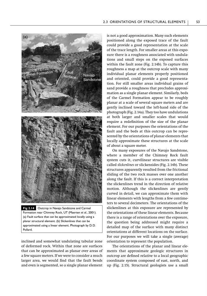
of the trace length. For smaller areas at this exposure there is a roughness associated with undulations and small steps on the exposed surfaces
within the fault zone (Fig. 2.14b). To capture this
roughness a map at the outcrop scale with many
individual planar elements properly positioned
and oriented, could provide a good representation. For still smaller areas individual grains of
sand provide a roughness that precludes approximation as a single planar element. Similarly, beds
of the Carmel Formation appear to be roughly
planar at a scale of several square meters and are
gently inclined toward the left-hand side of the
photograph (Fig. 2.14a). They too have undulations
at both larger and smaller scales that would
require a redefinition of the size of the planar
element. For our purposes the orientations of the
fault and the beds at this outcrop can be represented by the orientations of planar elements that
locally approximate these structures at the scale
of about a square meter.
On many exposures of the Navajo Sandstone,
where a member of the Chimney Rock fault
system cuts it, curvilinear structures are visible
called slickenlines or slickensides (Fig. 2.14b). These
structures apparently resulted from the frictional
sliding of the two rock masses over one another
along the fault. If this is a correct interpretation
the slickenlines trend in the direction of relative
motion. Although the slickenlines are gently
curved in detail, we can approximate them with
linear elements with lengths from a few centimeters to several decimeters. The orientations of the
slickenlines at this exposure are represented by
the orientations of these linear elements. Because
there is a range of orientations over the exposure,
the question being addressed might require a
detailed map of the surface with many distinct
orientations at different locations on the surface.
For our purposes we will take a single (average)
orientation to represent the population.
The orientations of the planar and linear elements that approximate geologic structures in
outcrop are defined relative to a local geographic
coordinate system composed of east, north, and
up (Fig. 2.15). Structural geologists use a small
2.3 ORIENTATIONS OF STRUCTURAL ELEMENTS
53
Ca rm el Fo rm ati on
Fa ul t
su rfa ce
Navajo
Sandstone
(a)
Fault surface
Sl ic ke nl in e
(b)
Fig 2.14 Outcrop in Navajo Sandstone and Carmel
Formation near Chimney Rock, UT (Maerten et al., 2001).
(a) Fault surface that can be approximated locally using a
planar structural element. (b) Slickenlines that can be
approximated using a linear element. Photograph by D. D.
Pollard.
of deformed rock. Within that zone are surfaces
that can be approximated as planar over areas of
a few square meters. If we were to consider a much
larger area, we would find that the fault bends
and even is segmented, so a single planar element
is not a good approximation. Many such elements
positioned along the exposed trace of the fault
could provide a good representation at the scale
of the trace length. For smaller areas at this exposure there is a roughness associated with undulations and small steps on the exposed surfaces
within the fault zone (Fig. 2.14b). To capture this
roughness a map at the outcrop scale with many
individual planar elements properly positioned
and oriented, could provide a good representation. For still smaller areas individual grains of
sand provide a roughness that precludes approximation as a single planar element. Similarly, beds
of the Carmel Formation appear to be roughly
planar at a scale of several square meters and are
gently inclined toward the left-hand side of the
photograph (Fig. 2.14a). They too have undulations
at both larger and smaller scales that would
require a redefinition of the size of the planar
element. For our purposes the orientations of the
fault and the beds at this outcrop can be represented by the orientations of planar elements that
locally approximate these structures at the scale
of about a square meter.
On many exposures of the Navajo Sandstone,
where a member of the Chimney Rock fault
system cuts it, curvilinear structures are visible
called slickenlines or slickensides (Fig. 2.14b). These
structures apparently resulted from the frictional
sliding of the two rock masses over one another
along the fault. If this is a correct interpretation
the slickenlines trend in the direction of relative
motion. Although the slickenlines are gently
curved in detail, we can approximate them with
linear elements with lengths from a few centimeters to several decimeters. The orientations of the
slickenlines at this exposure are represented by
the orientations of these linear elements. Because
there is a range of orientations over the exposure,
the question being addressed might require a
detailed map of the surface with many distinct
orientations at different locations on the surface.
For our purposes we will take a single (average)
orientation to represent the population.
The orientations of the planar and linear elements that approximate geologic structures in
outcrop are defined relative to a local geographic
coordinate system composed of east, north, and
up (Fig. 2.15). Structural geologists use a small
2.3 ORIENTATIONS OF STRUCTURAL ELEMENTS
53
Ca rm el Fo rm ati on
Fa ul t
su rfa ce
Navajo
Sandstone
(a)
Fault surface
Sl ic ke nl in e
(b)
Fig 2.14 Outcrop in Navajo Sandstone and Carmel
Formation near Chimney Rock, UT (Maerten et al., 2001).
(a) Fault surface that can be approximated locally using a
planar structural element. (b) Slickenlines that can be
approximated using a linear element. Photograph by D. D.
Pollard.