

hand-held instrument that combines a compass
and an inclinometer with bubble levels to
measure the necessary angles between the planar
or linear elements and this coordinate system.
Instructions for the use of such instruments are
found in books on geological field methods
(Compton, 1962; Davis and Reynolds, 1996) and
most students will be introduced to their use at
geological field camps. For the local coordinate
system “up” is determined as the opposite direction to the local gravitational acceleration using
the bubble levels, and this determines the horizontal plane that contains north and east. North
is measured with the compass (corrected for the
magnetic declination) and east is 90Њ clockwise
from north when looking down on the horizontal
plane.
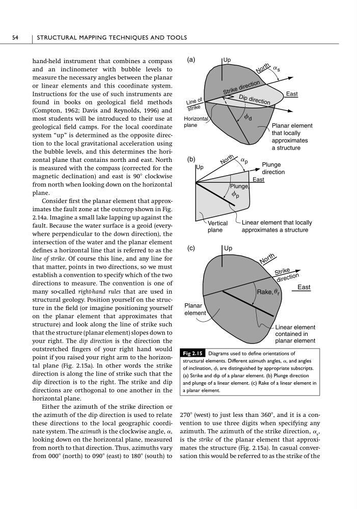
Consider first the planar element that approximates the fault zone at the outcrop shown in Fig.
2.14a. Imagine a small lake lapping up against the
fault. Because the water surface is a geoid (everywhere perpendicular to the down direction), the
intersection of the water and the planar element
defines a horizontal line that is referred to as the
line of strike. Of course this line, and any line for
that matter, points in two directions, so we must
establish a convention to specify which of the two
directions to measure. The convention is one of
many so-called right-hand rules that are used in
structural geology. Position yourself on the structure in the field (or imagine positioning yourself
on the planar element that approximates that
structure) and look along the line of strike such
that the structure (planar element) slopes down to
your right. The dip direction is the direction the
outstretched fingers of your right hand would
point if you raised your right arm to the horizontal plane (Fig. 2.15a). In other words the strike
direction is along the line of strike such that the
dip direction is to the right. The strike and dip
directions are orthogonal to one another in the
horizontal plane.
Either the azimuth of the strike direction or
the azimuth of the dip direction is used to relate
these directions to the local geographic coordinate system. The azimuth is the clockwise angle, ␣,
looking down on the horizontal plane, measured
from north to that direction. Thus, azimuths vary
from 000Њ (north) to 090Њ (east) to 180Њ (south) to
270Њ (west) to just less than 360Њ, and it is a convention to use three digits when specifying any
azimuth. The azimuth of the strike direction, ␣ s ,
is the strike of the planar element that approximates the structure (Fig. 2.15a). In casual conversation this would be referred to as the strike of the
54
STRUCTURAL MAPPING TECHNIQUES AND TOOLS
East
Up
(a)
D ip di re ct io n
N o r t h
Up
(b)
N o r t h
East
S tr ik e d ir e c ti o n
East
Up
(c)
N o r t h
Plunge,
Rake,
Planar element
that locally
approximates
a structure
Plunge
direction
Linear element that locally
approximates a structure
Vertical
plane
Planar
element
Linear element
contained in
planar element
a s
f d
Li ne of
st ri ke
Horizontal
plane
a p
f p
u r
S tr ik e
d ir e c ti o n
Fig 2.15 Diagrams used to define orientations of
structural elements. Different azimuth angles, ␣, and angles
of inclination, , are distinguished by appropriate subscripts.
(a) Strike and dip of a planar element. (b) Plunge direction
and plunge of a linear element. (c) Rake of a linear element in
a planar element.
and an inclinometer with bubble levels to
measure the necessary angles between the planar
or linear elements and this coordinate system.
Instructions for the use of such instruments are
found in books on geological field methods
(Compton, 1962; Davis and Reynolds, 1996) and
most students will be introduced to their use at
geological field camps. For the local coordinate
system “up” is determined as the opposite direction to the local gravitational acceleration using
the bubble levels, and this determines the horizontal plane that contains north and east. North
is measured with the compass (corrected for the
magnetic declination) and east is 90Њ clockwise
from north when looking down on the horizontal
plane.
Consider first the planar element that approximates the fault zone at the outcrop shown in Fig.
2.14a. Imagine a small lake lapping up against the
fault. Because the water surface is a geoid (everywhere perpendicular to the down direction), the
intersection of the water and the planar element
defines a horizontal line that is referred to as the
line of strike. Of course this line, and any line for
that matter, points in two directions, so we must
establish a convention to specify which of the two
directions to measure. The convention is one of
many so-called right-hand rules that are used in
structural geology. Position yourself on the structure in the field (or imagine positioning yourself
on the planar element that approximates that
structure) and look along the line of strike such
that the structure (planar element) slopes down to
your right. The dip direction is the direction the
outstretched fingers of your right hand would
point if you raised your right arm to the horizontal plane (Fig. 2.15a). In other words the strike
direction is along the line of strike such that the
dip direction is to the right. The strike and dip
directions are orthogonal to one another in the
horizontal plane.
Either the azimuth of the strike direction or
the azimuth of the dip direction is used to relate
these directions to the local geographic coordinate system. The azimuth is the clockwise angle, ␣,
looking down on the horizontal plane, measured
from north to that direction. Thus, azimuths vary
from 000Њ (north) to 090Њ (east) to 180Њ (south) to
270Њ (west) to just less than 360Њ, and it is a convention to use three digits when specifying any
azimuth. The azimuth of the strike direction, ␣ s ,
is the strike of the planar element that approximates the structure (Fig. 2.15a). In casual conversation this would be referred to as the strike of the
54
STRUCTURAL MAPPING TECHNIQUES AND TOOLS
East
Up
(a)
D ip di re ct io n
N o r t h
Up
(b)
N o r t h
East
S tr ik e d ir e c ti o n
East
Up
(c)
N o r t h
Plunge,
Rake,
Planar element
that locally
approximates
a structure
Plunge
direction
Linear element that locally
approximates a structure
Vertical
plane
Planar
element
Linear element
contained in
planar element
a s
f d
Li ne of
st ri ke
Horizontal
plane
a p
f p
u r
S tr ik e
d ir e c ti o n
Fig 2.15 Diagrams used to define orientations of
structural elements. Different azimuth angles, ␣, and angles
of inclination, , are distinguished by appropriate subscripts.
(a) Strike and dip of a planar element. (b) Plunge direction
and plunge of a linear element. (c) Rake of a linear element in
a planar element.