

(Muskhelishvili, 1954; Timoshenko and Goodier,
1970; Barber, 1992). To apply elasticity theory to
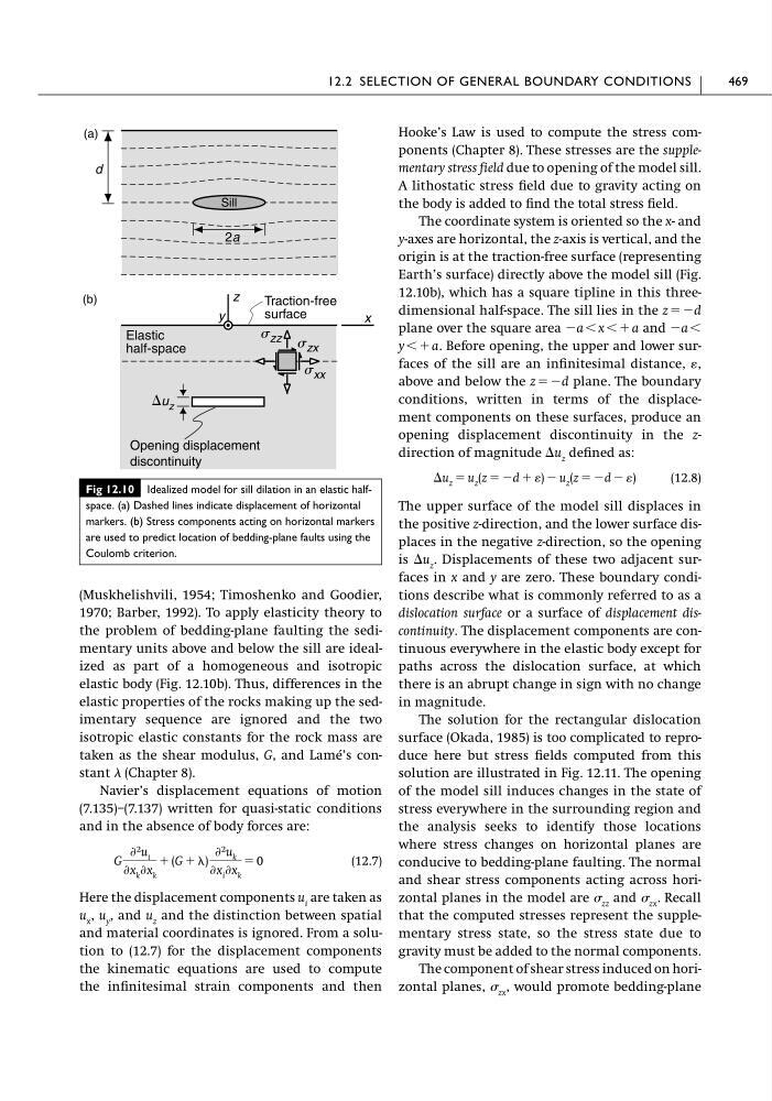
the problem of bedding-plane faulting the sedimentary units above and below the sill are idealized as part of a homogeneous and isotropic
elastic body (Fig. 12.10b). Thus, differences in the
elastic properties of the rocks making up the sedimentary sequence are ignored and the two
isotropic elastic constants for the rock mass are
taken as the shear modulus, G, and Lamé’s constant (Chapter 8).
Navier’s displacement equations of motion
(7.135)–(7.137) written for quasi-static conditions
and in the absence of body forces are:
(12.7)
Here the displacement components u i are taken as
u x , u y , and u z and the distinction between spatial
and material coordinates is ignored. From a solution to (12.7) for the displacement components
the kinematic equations are used to compute
the infinitesimal strain components and then
G
Ѩ 2 u i
Ѩx k Ѩx k
ϩ (G ϩ )
Ѩ 2 u k
Ѩx i Ѩx k
ϭ 0
Hooke’s Law is used to compute the stress components (Chapter 8). These stresses are the supplementary stress field due to opening of the model sill.
A lithostatic stress field due to gravity acting on
the body is added to find the total stress field.
The coordinate system is oriented so the x- and
y-axes are horizontal, the z-axis is vertical, and the
origin is at the traction-free surface (representing
Earth’s surface) directly above the model sill (Fig.
12.10b), which has a square tipline in this threedimensional half-space. The sill lies in the z ϭϪd
plane over the square area Ϫa Ͻ x Ͻϩa and Ϫa Ͻ
y Ͻϩa. Before opening, the upper and lower surfaces of the sill are an infinitesimal distance, ,
above and below the z ϭϪd plane. The boundary
conditions, written in terms of the displacement components on these surfaces, produce an
opening displacement discontinuity in the zdirection of magnitude ⌬u z defined as:
(12.8)
The upper surface of the model sill displaces in
the positive z-direction, and the lower surface displaces in the negative z-direction, so the opening
is ⌬u z . Displacements of these two adjacent surfaces in x and y are zero. These boundary conditions describe what is commonly referred to as a
dislocation surface or a surface of displacement discontinuity. The displacement components are continuous everywhere in the elastic body except for
paths across the dislocation surface, at which
there is an abrupt change in sign with no change
in magnitude.
The solution for the rectangular dislocation
surface (Okada, 1985) is too complicated to reproduce here but stress fields computed from this
solution are illustrated in Fig. 12.11. The opening
of the model sill induces changes in the state of
stress everywhere in the surrounding region and
the analysis seeks to identify those locations
where stress changes on horizontal planes are
conducive to bedding-plane faulting. The normal
and shear stress components acting across horizontal planes in the model are zz and zx . Recall
that the computed stresses represent the supplementary stress state, so the stress state due to
gravity must be added to the normal components.
The component of shear stress induced on horizontal planes, zx , would promote bedding-plane
⌬u z ϭ u z (z ϭ Ϫd ϩ ) Ϫ u z (z ϭ Ϫd Ϫ )
12.2 SELECTION OF GENERAL BOUNDARY CONDITIONS
469
Fig 12.10 Idealized model for sill dilation in an elastic halfspace. (a) Dashed lines indicate displacement of horizontal
markers. (b) Stress components acting on horizontal markers
are used to predict location of bedding-plane faults using the
Coulomb criterion.
x
z
(b)
2a
d
(a)
Elastic
half-space
Traction-free
surface
⌬u z
Sill
y
Opening displacement
discontinuity
s zz s zx
s xx
1970; Barber, 1992). To apply elasticity theory to
the problem of bedding-plane faulting the sedimentary units above and below the sill are idealized as part of a homogeneous and isotropic
elastic body (Fig. 12.10b). Thus, differences in the
elastic properties of the rocks making up the sedimentary sequence are ignored and the two
isotropic elastic constants for the rock mass are
taken as the shear modulus, G, and Lamé’s constant (Chapter 8).
Navier’s displacement equations of motion
(7.135)–(7.137) written for quasi-static conditions
and in the absence of body forces are:
(12.7)
Here the displacement components u i are taken as
u x , u y , and u z and the distinction between spatial
and material coordinates is ignored. From a solution to (12.7) for the displacement components
the kinematic equations are used to compute
the infinitesimal strain components and then
G
Ѩ 2 u i
Ѩx k Ѩx k
ϩ (G ϩ )
Ѩ 2 u k
Ѩx i Ѩx k
ϭ 0
Hooke’s Law is used to compute the stress components (Chapter 8). These stresses are the supplementary stress field due to opening of the model sill.
A lithostatic stress field due to gravity acting on
the body is added to find the total stress field.
The coordinate system is oriented so the x- and
y-axes are horizontal, the z-axis is vertical, and the
origin is at the traction-free surface (representing
Earth’s surface) directly above the model sill (Fig.
12.10b), which has a square tipline in this threedimensional half-space. The sill lies in the z ϭϪd
plane over the square area Ϫa Ͻ x Ͻϩa and Ϫa Ͻ
y Ͻϩa. Before opening, the upper and lower surfaces of the sill are an infinitesimal distance, ,
above and below the z ϭϪd plane. The boundary
conditions, written in terms of the displacement components on these surfaces, produce an
opening displacement discontinuity in the zdirection of magnitude ⌬u z defined as:
(12.8)
The upper surface of the model sill displaces in
the positive z-direction, and the lower surface displaces in the negative z-direction, so the opening
is ⌬u z . Displacements of these two adjacent surfaces in x and y are zero. These boundary conditions describe what is commonly referred to as a
dislocation surface or a surface of displacement discontinuity. The displacement components are continuous everywhere in the elastic body except for
paths across the dislocation surface, at which
there is an abrupt change in sign with no change
in magnitude.
The solution for the rectangular dislocation
surface (Okada, 1985) is too complicated to reproduce here but stress fields computed from this
solution are illustrated in Fig. 12.11. The opening
of the model sill induces changes in the state of
stress everywhere in the surrounding region and
the analysis seeks to identify those locations
where stress changes on horizontal planes are
conducive to bedding-plane faulting. The normal
and shear stress components acting across horizontal planes in the model are zz and zx . Recall
that the computed stresses represent the supplementary stress state, so the stress state due to
gravity must be added to the normal components.
The component of shear stress induced on horizontal planes, zx , would promote bedding-plane
⌬u z ϭ u z (z ϭ Ϫd ϩ ) Ϫ u z (z ϭ Ϫd Ϫ )
12.2 SELECTION OF GENERAL BOUNDARY CONDITIONS
469
Fig 12.10 Idealized model for sill dilation in an elastic halfspace. (a) Dashed lines indicate displacement of horizontal
markers. (b) Stress components acting on horizontal markers
are used to predict location of bedding-plane faults using the
Coulomb criterion.
x
z
(b)
2a
d
(a)
Elastic
half-space
Traction-free
surface
⌬u z
Sill
y
Opening displacement
discontinuity
s zz s zx
s xx