

Mountains as being “tongue-shaped” or roughly
anticlinal in plan with long axes extending radially from the intrusive centers. The elliptical plan
accounts for every shape from one of these endmembers to the other. The boundary conditions
at the distal edge of each plate are that both the
deflection and the slope are zero.
A uniform distribution of pressure, P ϭ constant, is defined as the difference between the
magma and lithostatic pressures, P m Ϫ P w . For
plates that are able to slide freely over one another
(no shear tractions across the interfaces), the
flexural rigidity is the sum of the individual
flexural rigidities, and we refer to this as the effective flexural rigidity, R e (Pollard and Johnson, 1973):
(12.2)
The plates are numbered from 1 to n starting at
the base of the stack (Fig. 12.6); h i is the thickness
of the ith plate; and Young’s modulus and
Poisson’s ratio for this plate are E i and i , respectively.
The solution to (12.1) for the deflection of any
one of the uniformly loaded elliptical plates is
(Love, 1944; Timoshenko and Woinowsky-Krieger,
1959):
(12.3)
The two end-member cases simplify this twodimensional problem to one spatial dimension
where the deflection distributions are:
(12.4)
(12.5)
The deflection distribution along any cross
section in the (x, z)-plane is the same for the anticlinal plan shape. The deflection distribution
along any radial line from the origin is the same
for the circular plan shape. Note that the deflection is directly proportional to the driving presw ϭ
(P m Ϫ P w )
64R e
(a 4 Ϫ 2a 2 x 2 ϩ x 4 ) (circular)
w ϭ
(P m Ϫ P w )
24R e
(a 4 Ϫ 2a 2 x 2 ϩ x 4 ) (anticlinal)
w ϭ
(P m Ϫ P w )
8R e Ά
΄ 1 Ϫ
x
a
2
Ϫ
y
c
2
΅
2
3
a 4 ϩ
2
a 2 c 2 ϩ
3
c 4
·
R e ϭ ͚
n
iϭ1
E i h i
3
12(1 Ϫ v 2
i )
sure and to the fourth power of the half-length, a,
so it is considerably more sensitive to changes in
the length of the plate, than to changes in pressure.
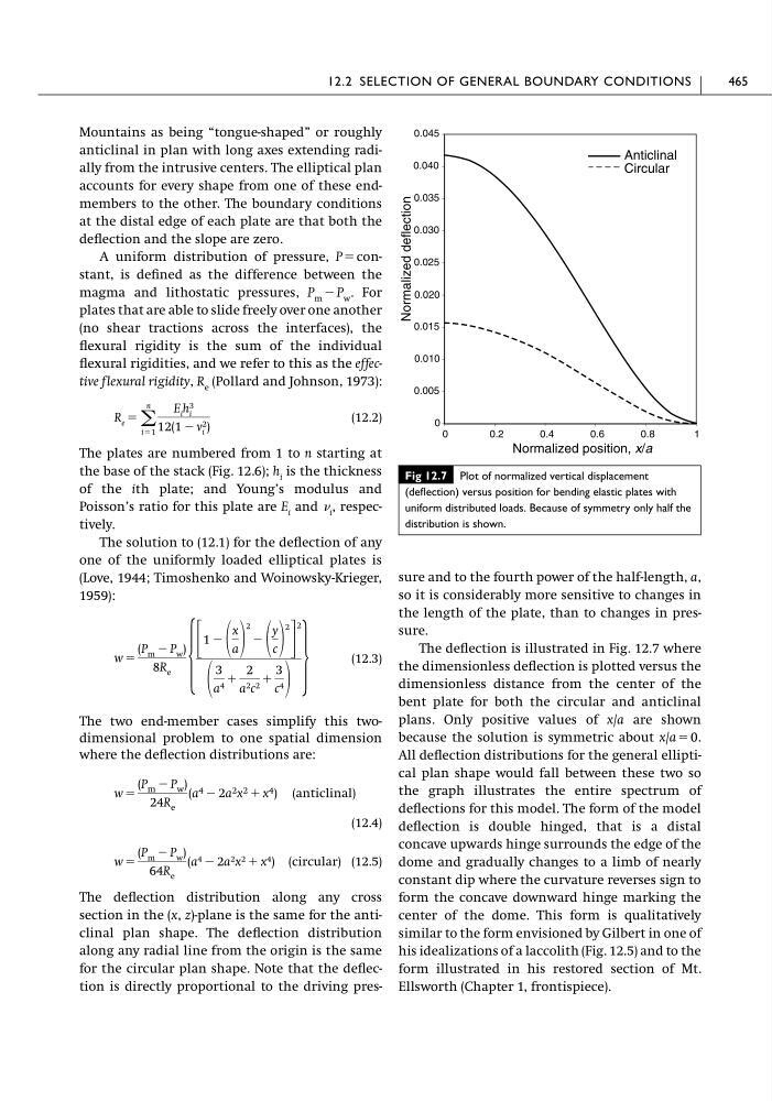
The deflection is illustrated in Fig. 12.7 where
the dimensionless deflection is plotted versus the
dimensionless distance from the center of the
bent plate for both the circular and anticlinal
plans. Only positive values of x/a are shown
because the solution is symmetric about x/a ϭ 0.
All deflection distributions for the general elliptical plan shape would fall between these two so
the graph illustrates the entire spectrum of
deflections for this model. The form of the model
deflection is double hinged, that is a distal
concave upwards hinge surrounds the edge of the
dome and gradually changes to a limb of nearly
constant dip where the curvature reverses sign to
form the concave downward hinge marking the
center of the dome. This form is qualitatively
similar to the form envisioned by Gilbert in one of
his idealizations of a laccolith (Fig. 12.5) and to the
form illustrated in his restored section of Mt.
Ellsworth (Chapter 1, frontispiece).
12.2 SELECTION OF GENERAL BOUNDARY CONDITIONS
465
Fig 12.7 Plot of normalized vertical displacement
(deflection) versus position for bending elastic plates with
uniform distributed loads. Because of symmetry only half the
distribution is shown.
0
0.005
0.010
0.015
0.020
0.025
0.030
0.035
0.040
0.045
0
0.2
0.4
0.6
0.8
1
Anticlinal
Circular
Normalized deflection
Normalized position, x/a
anticlinal in plan with long axes extending radially from the intrusive centers. The elliptical plan
accounts for every shape from one of these endmembers to the other. The boundary conditions
at the distal edge of each plate are that both the
deflection and the slope are zero.
A uniform distribution of pressure, P ϭ constant, is defined as the difference between the
magma and lithostatic pressures, P m Ϫ P w . For
plates that are able to slide freely over one another
(no shear tractions across the interfaces), the
flexural rigidity is the sum of the individual
flexural rigidities, and we refer to this as the effective flexural rigidity, R e (Pollard and Johnson, 1973):
(12.2)
The plates are numbered from 1 to n starting at
the base of the stack (Fig. 12.6); h i is the thickness
of the ith plate; and Young’s modulus and
Poisson’s ratio for this plate are E i and i , respectively.
The solution to (12.1) for the deflection of any
one of the uniformly loaded elliptical plates is
(Love, 1944; Timoshenko and Woinowsky-Krieger,
1959):
(12.3)
The two end-member cases simplify this twodimensional problem to one spatial dimension
where the deflection distributions are:
(12.4)
(12.5)
The deflection distribution along any cross
section in the (x, z)-plane is the same for the anticlinal plan shape. The deflection distribution
along any radial line from the origin is the same
for the circular plan shape. Note that the deflection is directly proportional to the driving presw ϭ
(P m Ϫ P w )
64R e
(a 4 Ϫ 2a 2 x 2 ϩ x 4 ) (circular)
w ϭ
(P m Ϫ P w )
24R e
(a 4 Ϫ 2a 2 x 2 ϩ x 4 ) (anticlinal)
w ϭ
(P m Ϫ P w )
8R e Ά
΄ 1 Ϫ
x
a
2
Ϫ
y
c
2
΅
2
3
a 4 ϩ
2
a 2 c 2 ϩ
3
c 4
·
R e ϭ ͚
n
iϭ1
E i h i
3
12(1 Ϫ v 2
i )
sure and to the fourth power of the half-length, a,
so it is considerably more sensitive to changes in
the length of the plate, than to changes in pressure.
The deflection is illustrated in Fig. 12.7 where
the dimensionless deflection is plotted versus the
dimensionless distance from the center of the
bent plate for both the circular and anticlinal
plans. Only positive values of x/a are shown
because the solution is symmetric about x/a ϭ 0.
All deflection distributions for the general elliptical plan shape would fall between these two so
the graph illustrates the entire spectrum of
deflections for this model. The form of the model
deflection is double hinged, that is a distal
concave upwards hinge surrounds the edge of the
dome and gradually changes to a limb of nearly
constant dip where the curvature reverses sign to
form the concave downward hinge marking the
center of the dome. This form is qualitatively
similar to the form envisioned by Gilbert in one of
his idealizations of a laccolith (Fig. 12.5) and to the
form illustrated in his restored section of Mt.
Ellsworth (Chapter 1, frontispiece).
12.2 SELECTION OF GENERAL BOUNDARY CONDITIONS
465
Fig 12.7 Plot of normalized vertical displacement
(deflection) versus position for bending elastic plates with
uniform distributed loads. Because of symmetry only half the
distribution is shown.
0
0.005
0.010
0.015
0.020
0.025
0.030
0.035
0.040
0.045
0
0.2
0.4
0.6
0.8
1
Anticlinal
Circular
Normalized deflection
Normalized position, x/a