

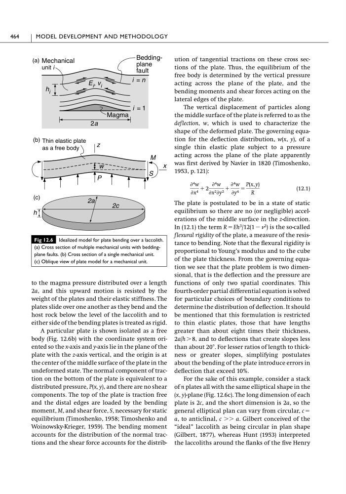
to the magma pressure distributed over a length
2a, and this upward motion is resisted by the
weight of the plates and their elastic stiffness. The
plates slide over one another as they bend and the
host rock below the level of the laccolith and to
either side of the bending plates is treated as rigid.
A particular plate is shown isolated as a free
body (Fig. 12.6b) with the coordinate system oriented so the x-axis and y-axis lie in the plane of the
plate with the z-axis vertical, and the origin is at
the center of the middle surface of the plate in the
undeformed state. The normal component of traction on the bottom of the plate is equivalent to a
distributed pressure, P(x, y), and there are no shear
components. The top of the plate is traction free
and the distal edges are loaded by the bending
moment, M, and shear force, S, necessary for static
equilibrium (Timoshenko, 1958; Timoshenko and
Woinowsky-Krieger, 1959). The bending moment
accounts for the distribution of the normal tractions and the shear force accounts for the distribution of tangential tractions on these cross sections of the plate. Thus, the equilibrium of the
free body is determined by the vertical pressure
acting across the plane of the plate, and the
bending moments and shear forces acting on the
lateral edges of the plate.
The vertical displacement of particles along
the middle surface of the plate is referred to as the
deflection, w, which is used to characterize the
shape of the deformed plate. The governing equation for the deflection distribution, w(x, y), of a
single thin elastic plate subject to a pressure
acting across the plane of the plate apparently
was first derived by Navier in 1820 (Timoshenko,
1953, p. 121):
(12.1)
The plate is postulated to be in a state of static
equilibrium so there are no (or negligible) accelerations of the middle surface in the z-direction.
In (12.1) the term R ϭ Eh
3 /12(1 Ϫ
2 ) is the so-called
flexural rigidity of the plate, a measure of the resistance to bending. Note that the flexural rigidity is
proportional to Young’s modulus and to the cube
of the plate thickness. From the governing equation we see that the plate problem is two dimensional, that is the deflection and the pressure are
functions of only two spatial coordinates. This
fourth-order partial differential equation is solved
for particular choices of boundary conditions to
determine the distribution of deflection. It should
be mentioned that this formulation is restricted
to thin elastic plates, those that have lengths
greater than about eight times their thickness,
2a/h Ͼ 8, and to deflections that create slopes less
than about 20Њ. For lesser ratios of length to thickness or greater slopes, simplifying postulates
about the bending of the plate introduce errors in
deflection that exceed 10%.
For the sake of this example, consider a stack
of n plates all with the same elliptical shape in the
(x, y)-plane (Fig. 12.6c). The long dimension of each
plate is 2c, and the short dimension is 2a, so the
general elliptical plan can vary from circular, c ϭ
a, to anticlinal, c ϾϾ a. Gilbert conceived of the
“ideal” laccolith as being circular in plan shape
(Gilbert, 1877), whereas Hunt (1953) interpreted
the laccoliths around the flanks of the five Henry
Ѩ 4 w
Ѩx 4 ϩ 2
Ѩ 4 w
Ѩx 2 Ѩy 2 ϩ
Ѩ 4 w
Ѩy 4 ϭ
P(x, y)
R
464
MODEL DEVELOPMENT AND METHODOLOGY
Fig 12.6 Idealized model for plate bending over a laccolith.
(a) Cross section of multiple mechanical units with beddingplane faults. (b) Cross section of a single mechanical unit.
(c) Oblique view of plate model for a mechanical unit.
x
z
(b)
(a)
P
w
Thin elastic plate
as a free body
S
M
2a
Beddingplane
fault
i = 1
i = n
Mechanical
unit i
Magma
h i
E i , v i
(c)
2c
2a
h
2a, and this upward motion is resisted by the
weight of the plates and their elastic stiffness. The
plates slide over one another as they bend and the
host rock below the level of the laccolith and to
either side of the bending plates is treated as rigid.
A particular plate is shown isolated as a free
body (Fig. 12.6b) with the coordinate system oriented so the x-axis and y-axis lie in the plane of the
plate with the z-axis vertical, and the origin is at
the center of the middle surface of the plate in the
undeformed state. The normal component of traction on the bottom of the plate is equivalent to a
distributed pressure, P(x, y), and there are no shear
components. The top of the plate is traction free
and the distal edges are loaded by the bending
moment, M, and shear force, S, necessary for static
equilibrium (Timoshenko, 1958; Timoshenko and
Woinowsky-Krieger, 1959). The bending moment
accounts for the distribution of the normal tractions and the shear force accounts for the distribution of tangential tractions on these cross sections of the plate. Thus, the equilibrium of the
free body is determined by the vertical pressure
acting across the plane of the plate, and the
bending moments and shear forces acting on the
lateral edges of the plate.
The vertical displacement of particles along
the middle surface of the plate is referred to as the
deflection, w, which is used to characterize the
shape of the deformed plate. The governing equation for the deflection distribution, w(x, y), of a
single thin elastic plate subject to a pressure
acting across the plane of the plate apparently
was first derived by Navier in 1820 (Timoshenko,
1953, p. 121):
(12.1)
The plate is postulated to be in a state of static
equilibrium so there are no (or negligible) accelerations of the middle surface in the z-direction.
In (12.1) the term R ϭ Eh
3 /12(1 Ϫ
2 ) is the so-called
flexural rigidity of the plate, a measure of the resistance to bending. Note that the flexural rigidity is
proportional to Young’s modulus and to the cube
of the plate thickness. From the governing equation we see that the plate problem is two dimensional, that is the deflection and the pressure are
functions of only two spatial coordinates. This
fourth-order partial differential equation is solved
for particular choices of boundary conditions to
determine the distribution of deflection. It should
be mentioned that this formulation is restricted
to thin elastic plates, those that have lengths
greater than about eight times their thickness,
2a/h Ͼ 8, and to deflections that create slopes less
than about 20Њ. For lesser ratios of length to thickness or greater slopes, simplifying postulates
about the bending of the plate introduce errors in
deflection that exceed 10%.
For the sake of this example, consider a stack
of n plates all with the same elliptical shape in the
(x, y)-plane (Fig. 12.6c). The long dimension of each
plate is 2c, and the short dimension is 2a, so the
general elliptical plan can vary from circular, c ϭ
a, to anticlinal, c ϾϾ a. Gilbert conceived of the
“ideal” laccolith as being circular in plan shape
(Gilbert, 1877), whereas Hunt (1953) interpreted
the laccoliths around the flanks of the five Henry
Ѩ 4 w
Ѩx 4 ϩ 2
Ѩ 4 w
Ѩx 2 Ѩy 2 ϩ
Ѩ 4 w
Ѩy 4 ϭ
P(x, y)
R
464
MODEL DEVELOPMENT AND METHODOLOGY
Fig 12.6 Idealized model for plate bending over a laccolith.
(a) Cross section of multiple mechanical units with beddingplane faults. (b) Cross section of a single mechanical unit.
(c) Oblique view of plate model for a mechanical unit.
x
z
(b)
(a)
P
w
Thin elastic plate
as a free body
S
M
2a
Beddingplane
fault
i = 1
i = n
Mechanical
unit i
Magma
h i
E i , v i
(c)
2c
2a
h