

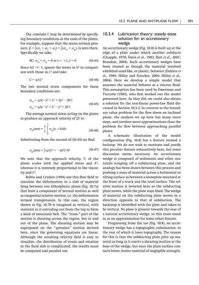
The constant C may be determined by specifying boundary conditions at the ends of the plates.
For example, suppose that the mean normal pressure,
, is zero there.
Specifically we take:
(10.43)
Since h/L � � 1, ignore the terms in h
2 in comparison with those in L
2 and take:
(10.44)
The two normal stress components for these
boundary conditions are:
(10.45)
The average normal stress acting on the plates
to produce an approach velocity of 2V is:
(10.46)
Substituting from the second of (10.45) we find:
(10.47)
We note that the approach velocity, V, of the
plates scales with the applied stress and h
3 ,
whereas it is inversely proportional to the viscosity and L
2 .
Robin and Cruden (1994) use this flow field to
simulate the deformation in a slab of material
lying between two lithospheric plates (Fig. 10.7a)
that have a component of normal motion as well
as tangential relative motion, i.e. the deformation
termed transpression. In this case, the region
shown in Fig. 10.7b is imagined as vertical, with
material in it extruding out from the top to form
a kind of mountain belt. The “trans-” part of the
motion is shearing across the region, but in and
out of the plane. The shearing motion may be
superposed on the “-pression” motion derived
here, since the governing equations are linear.
Although the resulting velocity field is easy to
visualize, the distribution of strain and rotation
in the fluid slab is complicated; the results must
be computed and puzzled out.
� yy (ave) �
2
3 � AL 2 � ��VL 2 �h 3
� yy (ave) �
1
L Ύ
L
0
� yy (x, �h) dx
� yy � � A(�x 2 � L 2 � y 2 � 2h 2 )
� xx � � A(�x 2 � L 2 � 3y 2 � 2h 2 )
C � � AL 2
BC: � xx � � yy � 0 at x � �L, y � 0
p �
1
3 (� 1 � � 2 � � 3 ) �
1
2 (� xx � � yy )
10.3.4 Lubrication theory: steady-state
solution for an accretionary
wedge
An accretionary wedge (Fig. 10.8) is built up at the
edge of a plate under which another subducts
(Chapple, 1978; Davis et al., 1983; Batt et al., 2001;
Brandon, 2004). Such accretionary wedges have
been treated as though the material involved
exhibited sand-like, or plastic, behavior (Dahlen et
al., 1984; Hilley and Strecker, 2004; Hilley et al.,
2004). Here we develop a simple model that
assumes the material behaves as a viscous fluid.
This assumption has been used by Emerman and
Turcotte (1983), who first worked out the model
presented here. As they did, we could also obtain
a solution for the non-linear power-law fluid discussed in Section 10.3.2. In contrast to the boundary value problem for the flow down an inclined
plane, the analysis set up here has many more
steps, and involves more approximations than the
problem for flow between approaching parallel
plates.
A schematic illustration of the model
configuration (Fig. 10.8) has a feature termed a
backstop. We do not wish to motivate and justify
this peculiar feature exhaustively here, but some
discussion seems necessary. An accretionary
wedge is composed of sediments and other materials scraping off a subducting plate, and the
analogy has been drawn between this process and
pushing a mass of material across a horizontal or
tilting surface as between a snowplow mounted at
the front of a truck and the road surface. The relative motion is inverted here so the subducting
plate moves, while the plow stays fixed. The wedge
of material on the subducting plate moves in a
direction opposite to that of subduction. The
backstop is identified with the plow and taken to
be vertical. No plow is present towards the rear of
a natural accretionary wedge, so this must stand
in as an approximation for some other feature.
Progressing from the toe (Fig. 10.8), an accretionary wedge has a topographic culmination, to
the rear of which it loses topography. The reason
for this is that the subducting plate piles up material as long as it exerts a shearing motion at the
base of the wedge, but once the plate surface contacts lower, hotter material of negligible strength,
10.3 PLANE AND ANTIPLANE FLOW
393
For example, suppose that the mean normal pressure,
, is zero there.
Specifically we take:
(10.43)
Since h/L � � 1, ignore the terms in h
2 in comparison with those in L
2 and take:
(10.44)
The two normal stress components for these
boundary conditions are:
(10.45)
The average normal stress acting on the plates
to produce an approach velocity of 2V is:
(10.46)
Substituting from the second of (10.45) we find:
(10.47)
We note that the approach velocity, V, of the
plates scales with the applied stress and h
3 ,
whereas it is inversely proportional to the viscosity and L
2 .
Robin and Cruden (1994) use this flow field to
simulate the deformation in a slab of material
lying between two lithospheric plates (Fig. 10.7a)
that have a component of normal motion as well
as tangential relative motion, i.e. the deformation
termed transpression. In this case, the region
shown in Fig. 10.7b is imagined as vertical, with
material in it extruding out from the top to form
a kind of mountain belt. The “trans-” part of the
motion is shearing across the region, but in and
out of the plane. The shearing motion may be
superposed on the “-pression” motion derived
here, since the governing equations are linear.
Although the resulting velocity field is easy to
visualize, the distribution of strain and rotation
in the fluid slab is complicated; the results must
be computed and puzzled out.
� yy (ave) �
2
3 � AL 2 � ��VL 2 �h 3
� yy (ave) �
1
L Ύ
L
0
� yy (x, �h) dx
� yy � � A(�x 2 � L 2 � y 2 � 2h 2 )
� xx � � A(�x 2 � L 2 � 3y 2 � 2h 2 )
C � � AL 2
BC: � xx � � yy � 0 at x � �L, y � 0
p �
1
3 (� 1 � � 2 � � 3 ) �
1
2 (� xx � � yy )
10.3.4 Lubrication theory: steady-state
solution for an accretionary
wedge
An accretionary wedge (Fig. 10.8) is built up at the
edge of a plate under which another subducts
(Chapple, 1978; Davis et al., 1983; Batt et al., 2001;
Brandon, 2004). Such accretionary wedges have
been treated as though the material involved
exhibited sand-like, or plastic, behavior (Dahlen et
al., 1984; Hilley and Strecker, 2004; Hilley et al.,
2004). Here we develop a simple model that
assumes the material behaves as a viscous fluid.
This assumption has been used by Emerman and
Turcotte (1983), who first worked out the model
presented here. As they did, we could also obtain
a solution for the non-linear power-law fluid discussed in Section 10.3.2. In contrast to the boundary value problem for the flow down an inclined
plane, the analysis set up here has many more
steps, and involves more approximations than the
problem for flow between approaching parallel
plates.
A schematic illustration of the model
configuration (Fig. 10.8) has a feature termed a
backstop. We do not wish to motivate and justify
this peculiar feature exhaustively here, but some
discussion seems necessary. An accretionary
wedge is composed of sediments and other materials scraping off a subducting plate, and the
analogy has been drawn between this process and
pushing a mass of material across a horizontal or
tilting surface as between a snowplow mounted at
the front of a truck and the road surface. The relative motion is inverted here so the subducting
plate moves, while the plow stays fixed. The wedge
of material on the subducting plate moves in a
direction opposite to that of subduction. The
backstop is identified with the plow and taken to
be vertical. No plow is present towards the rear of
a natural accretionary wedge, so this must stand
in as an approximation for some other feature.
Progressing from the toe (Fig. 10.8), an accretionary wedge has a topographic culmination, to
the rear of which it loses topography. The reason
for this is that the subducting plate piles up material as long as it exerts a shearing motion at the
base of the wedge, but once the plate surface contacts lower, hotter material of negligible strength,
10.3 PLANE AND ANTIPLANE FLOW
393