

surface area is oriented approximately perpendicular to the local maximum tensile stress. This simple
conceptual model may require modification to
explain features of some opening fractures such as
a process zone of microcracks (Fig. 9.18), or the
development of plastic deformation beyond the
near-tip region, or the propagation of fractures in
non-elastic materials, but tools exist in the literature of fracture mechanics to investigate these phenomena (Kanninen and Popelar, 1985; Renshaw
and Harvey, 1994; Anderson, 1995).
9.5.2 Growth of faults in granite and
sandstone
In contrast to opening fractures, the development
of faults apparently is a more complicated process
that can involve several different physical mechanisms which are not readily conceptualized in
terms of the propagation of a fracture tipline and
the increase in area of two surfaces that formerly
were bonded together. As an example we consider
the growth of faults in granitic rock of the Sierra
Nevada, California, in the Late Cretaceous (Segall
et al., 1990). The oldest fracturing event, probably
related to cooling of the Lake Edison Granodiorite,
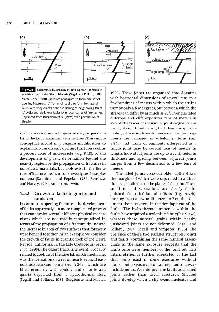
was the formation of a set of nearly vertical eastnortheast-striking joints (Fig. 9.36a), which are
filled primarily with epidote and chlorite and
quartz deposited from a hydrothermal fluid
(Segall and Pollard, 1983; Bergbauer and Martel,
1999). These joints are organized into domains
with horizontal dimensions of several tens to a
few hundreds of meters within which the strikes
vary by only a few degrees, but between which the
strikes can differ by as much as 20Њ. Over glaciated
outcrops and cliff exposures tens of meters in
extent the traces of individual joint segments are
nearly straight, indicating that they are approximately planar in three dimensions. The joint segments are arranged in echelon patterns (Fig.
9.37a) and trains of segments interpreted as a
single joint may be several tens of meters in
length. Individual joints are up to a centimeter in
thickness and spacing between adjacent joints
ranges from a few decimeters to a few tens of
meters.
The filled joints cross-cut older aplite dikes,
the margins of which were separated in a direction perpendicular to the plane of the joint. These
small normal separations are clearly distinguished from left-lateral offsets (Fig. 9.37b),
ranging from a few millimeters to 2 m, that document the next event in the development of the
faults. The hydrothermal minerals within the
faults have acquired a mylonitic fabric (Fig. 9.37c),
whereas those mineral grains within nearby
unsheared joints are not deformed (Segall and
Pollard, 1983; Segall and Simpson, 1986). The
presence of these two parallel structures, joints
and faults, containing the same mineral assemblage in the same exposure suggests that the
faults once were members of the joint set. This
interpretation is further supported by the fact
that joints exist in some exposures without
faults, but exposures containing faults always
include joints. We interpret the faults as sheared
joints rather than shear fractures. Sheared
joints develop when a slip event nucleates and
378
BRITTLE BEHAVIOR
Fig 9.36 Schematic illustration of development of faults in
granitic rocks of the Sierra Nevada (Segall and Pollard, 1983;
Martel et al., 1988). (a) Joints propagate to form one set of
opening fractures. (b) Some joints slip to form left-lateral
faults with wing cracks near tips linking to neighboring faults.
(c) Adjacent left-lateral faults form boundaries of fault zones.
Reprinted from Bürgmann et al. (1994) with permission of
Elsevier.
(a)
(b)
(c)
Joints
Dike
Unfaulted
joint
Single
faults
Fault zone
Right step
Left step
Splay fractures
conceptual model may require modification to
explain features of some opening fractures such as
a process zone of microcracks (Fig. 9.18), or the
development of plastic deformation beyond the
near-tip region, or the propagation of fractures in
non-elastic materials, but tools exist in the literature of fracture mechanics to investigate these phenomena (Kanninen and Popelar, 1985; Renshaw
and Harvey, 1994; Anderson, 1995).
9.5.2 Growth of faults in granite and
sandstone
In contrast to opening fractures, the development
of faults apparently is a more complicated process
that can involve several different physical mechanisms which are not readily conceptualized in
terms of the propagation of a fracture tipline and
the increase in area of two surfaces that formerly
were bonded together. As an example we consider
the growth of faults in granitic rock of the Sierra
Nevada, California, in the Late Cretaceous (Segall
et al., 1990). The oldest fracturing event, probably
related to cooling of the Lake Edison Granodiorite,
was the formation of a set of nearly vertical eastnortheast-striking joints (Fig. 9.36a), which are
filled primarily with epidote and chlorite and
quartz deposited from a hydrothermal fluid
(Segall and Pollard, 1983; Bergbauer and Martel,
1999). These joints are organized into domains
with horizontal dimensions of several tens to a
few hundreds of meters within which the strikes
vary by only a few degrees, but between which the
strikes can differ by as much as 20Њ. Over glaciated
outcrops and cliff exposures tens of meters in
extent the traces of individual joint segments are
nearly straight, indicating that they are approximately planar in three dimensions. The joint segments are arranged in echelon patterns (Fig.
9.37a) and trains of segments interpreted as a
single joint may be several tens of meters in
length. Individual joints are up to a centimeter in
thickness and spacing between adjacent joints
ranges from a few decimeters to a few tens of
meters.
The filled joints cross-cut older aplite dikes,
the margins of which were separated in a direction perpendicular to the plane of the joint. These
small normal separations are clearly distinguished from left-lateral offsets (Fig. 9.37b),
ranging from a few millimeters to 2 m, that document the next event in the development of the
faults. The hydrothermal minerals within the
faults have acquired a mylonitic fabric (Fig. 9.37c),
whereas those mineral grains within nearby
unsheared joints are not deformed (Segall and
Pollard, 1983; Segall and Simpson, 1986). The
presence of these two parallel structures, joints
and faults, containing the same mineral assemblage in the same exposure suggests that the
faults once were members of the joint set. This
interpretation is further supported by the fact
that joints exist in some exposures without
faults, but exposures containing faults always
include joints. We interpret the faults as sheared
joints rather than shear fractures. Sheared
joints develop when a slip event nucleates and
378
BRITTLE BEHAVIOR
Fig 9.36 Schematic illustration of development of faults in
granitic rocks of the Sierra Nevada (Segall and Pollard, 1983;
Martel et al., 1988). (a) Joints propagate to form one set of
opening fractures. (b) Some joints slip to form left-lateral
faults with wing cracks near tips linking to neighboring faults.
(c) Adjacent left-lateral faults form boundaries of fault zones.
Reprinted from Bürgmann et al. (1994) with permission of
Elsevier.
(a)
(b)
(c)
Joints
Dike
Unfaulted
joint
Single
faults
Fault zone
Right step
Left step
Splay fractures