

To solve the dilemma Griffith proposed to
eliminate 0 from these equations by relating it to
the uniaxial tensile strength, T u . Considering the
symmetric case,  c ϭ 90Њ, he suggested that a laboratory specimen would fail if
(here we
added the internal pressure). Substituting this
relationship into (9.68) we have
This is the predicted stress at the tip of the most
dangerous symmetric flaw just as a fracture initiates. Substituting this relationship into (9.67) and
(9.68), the unwanted term 0 is eliminated, leaving
the Griffith criteria for failure. If
then:
(9.69)
In this case a crack would propagate away from
the inclined flaw oblique to its long axis, forming
a so-called wing crack (Segall and Pollard, 1983;
Cruikshank and Aydin, 1995; Cooke, 1997;
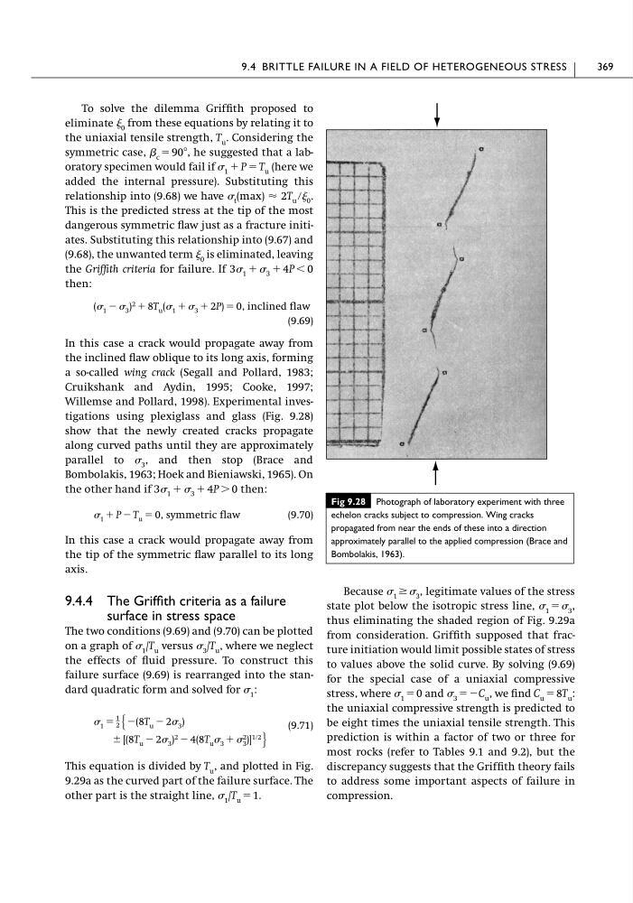
Willemse and Pollard, 1998). Experimental investigations using plexiglass and glass (Fig. 9.28)
show that the newly created cracks propagate
along curved paths until they are approximately
parallel to 3 , and then stop (Brace and
Bombolakis, 1963; Hoek and Bieniawski, 1965). On
the other hand if
then:
(9.70)
In this case a crack would propagate away from
the tip of the symmetric flaw parallel to its long
axis.
9.4.4 The Griffith criteria as a failure
surface in stress space
The two conditions (9.69) and (9.70) can be plotted
on a graph of 1 /T u versus 3 /T u , where we neglect
the effects of fluid pressure. To construct this
failure surface (9.69) is rearranged into the standard quadratic form and solved for 1 :
(9.71)
This equation is divided by T u , and plotted in Fig.
9.29a as the curved part of the failure surface. The
other part is the straight line, 1 /T u ϭ 1.
Ϯ [(8T u Ϫ 2 3 ) 2 Ϫ 4(8T u 3 ϩ 2
3 )] 1ր2 ·
1 ϭ
1
2 Ά Ϫ(8T u Ϫ 2 3 )
1 ϩ P Ϫ T u ϭ 0, symmetric flaw
3 1 ϩ 3 ϩ 4P Ͼ 0
( 1 Ϫ 3 ) 2 ϩ 8T u ( 1 ϩ 3 ϩ 2P) ϭ 0, inclined flaw
3 1 ϩ 3 ϩ 4P Ͻ 0
t (max) Ϸ 2T u ր 0 .
1 ϩ P ϭ T u
Because 1 Ն 3 , legitimate values of the stress
state plot below the isotropic stress line, 1 ϭ 3 ,
thus eliminating the shaded region of Fig. 9.29a
from consideration. Griffith supposed that fracture initiation would limit possible states of stress
to values above the solid curve. By solving (9.69)
for the special case of a uniaxial compressive
stress, where 1 ϭ 0 and 3 ϭϪC u , we find C u ϭ 8T u :
the uniaxial compressive strength is predicted to
be eight times the uniaxial tensile strength. This
prediction is within a factor of two or three for
most rocks (refer to Tables 9.1 and 9.2), but the
discrepancy suggests that the Griffith theory fails
to address some important aspects of failure in
compression.
9.4 BRITTLE FAILURE IN A FIELD OF HETEROGENEOUS STRESS
369
Fig 9.28 Photograph of laboratory experiment with three
echelon cracks subject to compression. Wing cracks
propagated from near the ends of these into a direction
approximately parallel to the applied compression (Brace and
Bombolakis, 1963).
eliminate 0 from these equations by relating it to
the uniaxial tensile strength, T u . Considering the
symmetric case,  c ϭ 90Њ, he suggested that a laboratory specimen would fail if
(here we
added the internal pressure). Substituting this
relationship into (9.68) we have
This is the predicted stress at the tip of the most
dangerous symmetric flaw just as a fracture initiates. Substituting this relationship into (9.67) and
(9.68), the unwanted term 0 is eliminated, leaving
the Griffith criteria for failure. If
then:
(9.69)
In this case a crack would propagate away from
the inclined flaw oblique to its long axis, forming
a so-called wing crack (Segall and Pollard, 1983;
Cruikshank and Aydin, 1995; Cooke, 1997;
Willemse and Pollard, 1998). Experimental investigations using plexiglass and glass (Fig. 9.28)
show that the newly created cracks propagate
along curved paths until they are approximately
parallel to 3 , and then stop (Brace and
Bombolakis, 1963; Hoek and Bieniawski, 1965). On
the other hand if
then:
(9.70)
In this case a crack would propagate away from
the tip of the symmetric flaw parallel to its long
axis.
9.4.4 The Griffith criteria as a failure
surface in stress space
The two conditions (9.69) and (9.70) can be plotted
on a graph of 1 /T u versus 3 /T u , where we neglect
the effects of fluid pressure. To construct this
failure surface (9.69) is rearranged into the standard quadratic form and solved for 1 :
(9.71)
This equation is divided by T u , and plotted in Fig.
9.29a as the curved part of the failure surface. The
other part is the straight line, 1 /T u ϭ 1.
Ϯ [(8T u Ϫ 2 3 ) 2 Ϫ 4(8T u 3 ϩ 2
3 )] 1ր2 ·
1 ϭ
1
2 Ά Ϫ(8T u Ϫ 2 3 )
1 ϩ P Ϫ T u ϭ 0, symmetric flaw
3 1 ϩ 3 ϩ 4P Ͼ 0
( 1 Ϫ 3 ) 2 ϩ 8T u ( 1 ϩ 3 ϩ 2P) ϭ 0, inclined flaw
3 1 ϩ 3 ϩ 4P Ͻ 0
t (max) Ϸ 2T u ր 0 .
1 ϩ P ϭ T u
Because 1 Ն 3 , legitimate values of the stress
state plot below the isotropic stress line, 1 ϭ 3 ,
thus eliminating the shaded region of Fig. 9.29a
from consideration. Griffith supposed that fracture initiation would limit possible states of stress
to values above the solid curve. By solving (9.69)
for the special case of a uniaxial compressive
stress, where 1 ϭ 0 and 3 ϭϪC u , we find C u ϭ 8T u :
the uniaxial compressive strength is predicted to
be eight times the uniaxial tensile strength. This
prediction is within a factor of two or three for
most rocks (refer to Tables 9.1 and 9.2), but the
discrepancy suggests that the Griffith theory fails
to address some important aspects of failure in
compression.
9.4 BRITTLE FAILURE IN A FIELD OF HETEROGENEOUS STRESS
369
Fig 9.28 Photograph of laboratory experiment with three
echelon cracks subject to compression. Wing cracks
propagated from near the ends of these into a direction
approximately parallel to the applied compression (Brace and
Bombolakis, 1963).